PIC 、APIC(IOAPIC LAPIC)
PIC全称Programmable Interrupt Controller,通常是指Intel 8259A双片级联构成的最多支持15个interrupts的中断控制系统。APIC全称Advanced Programmable Interrupt Controller,APIC是为了多核平台而设计的。它由两个部分组成IOAPIC和LAPIC,其中IOAPIC通常位于南桥中
2. PIC
基于Intel 80x86的PC使用两片8259A级联的方式组成了可以管理15级中断向量的一个中断系统,下图是它的一个连接示意图。两片8259A,一片为Master,另一片为Slaver。其中Slaver的INT接到Master的IRQ2上。8259A有两种工作模式分别为编程和操作模式。BIOS初始化的时候会先通过IO port对8259A进行编程配置,在此之后8259A就可以响应来自外部设备的中断请求了。Master的IO address是0x20 0x21; Slaver的IO address是0xA0 0xA1。
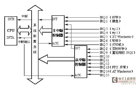
为了能够正常的使用PIC来管理系统中断,就需要对它进行初始化。8259A支持两种类型的命令字,一类是初始化命令字ICW1~4,另一类是操作命令字OCW1~3,其中每一个命令字的各个bit都有其代表的特定意义。下述是一个初始化Master的一个sample code:
MOV
OUT
MOV
OUT
MOV
OUT
MOV
OUT
3. APIC
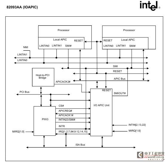
Intel APIC由一组中断输入信号,一个24*64bit的Programmable Redirection Table(PRT),一组register和用于从APIC BUS(FSB/QPI)上传送APIC MSG的部件组成,当南桥的IO device通过IOAPIC的interrupt lines产生interrupt,IOAPIC将根据内部的PRT table格式化成中断请求信息,并将该信息发送给目标CPU的LAPIC,再由LAPIC通知CPU进行处理。下图是一个基于Intel APIC的连接示意图,如下图所示IOAPIC上有24个interrupt pin,每一个pin都对应一个RTE,所以针对每一个interrupt pin都可以单独设定它的mask,触发方式(level,edge trigger),中断管脚的极性,传送方式,传送状态,目的地,中断向量等。
Programmable Redirection Table详细格式如下所示:
Bit Description: |
[63:56] Destination Field—R/W. |
[59:56] contain an APIC ID. If Logical Mode is selected (bit 11=1), the Destination Field potentially defines a set of processors. Bits [63:56] of the Destination Field specify the logical destination address. Destination Mode IOREDTBLx[11] Logical Destination Address 0, Physical Mode IOREDTBLx[59:56] = APIC ID 1, Logical Mode IOREDTBLx[63:56] = Set of processors |
[55:17] Reserved.82093AA (IOAPIC) |
[16] interrupts signaled on a masked interrupt pin are ignored (i.e., not delivered or held pending). Level-asserts or negates occurring on a masked level-sensitive pin are also ignored and have no side effects. Changing the mask bit from unmasked to masked after the interrupt is accepted by a local APIC has no effect on that interrupt. This behavior is identical to the case where the device withdraws the interrupt before that interrupt is posted to the processor. It is softwares responsibility to handle the case where the mask bit is set after the interrupt message has been accepted by a local APIC unit but before the interrupt is dispensed to the processor. When this bit is 0, the interrupt is not masked. An edge or level on an interrupt pin that is not masked results in the delivery of the interrupt to the destination. |
[15] Trigger Mode—R/W. |
[14] Remote I |
PICAPICIOAPICLAPI 相关文章:
- Windows CE 进程、线程和内存管理(11-09)
- RedHatLinux新手入门教程(5)(11-12)
- uClinux介绍(11-09)
- openwebmailV1.60安装教学(11-12)
- Linux嵌入式系统开发平台选型探讨(11-09)
- Windows CE 进程、线程和内存管理(二)(11-09)