Automotive Linear Regulators M
Lowest Possible Quiescent Current for Always-On Functions
The receiver of a remote keyless entry (RKE) system (Figure 3) must be always active, so at any time it can detect the commands issued by the remote controller in the key. You cannot disable the power supply of an RKE receiver, so its circuitry should draw the lowest possible quiescent current, especially in stand-by mode. It must then supply a normal operating current as soon as it awakens.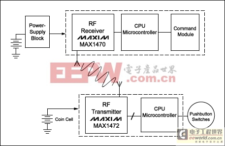
Figure 3. A typical RKE system consists of the car-mounted side and the key-mounted side. Because the car's power supply block connects directly to the battery, its quiescent current must be low.< /I>
We must, therefore, optimize the power supply block (top left corner) in terms of minimizing quiescent current. Aside from low quiescent current, requirements on the internal linear regulator are not very stringent. It must simply provide an input, an output, and a ground pin. Shutdown and Enable functions are not required because the receiver is always powered. But, we must look closely at the way it sets the output voltage. Many linear regulators set the output voltage using an external resistor-divider, but that is probably not a good idea for this application. Consider the following scenario.
The MAX1470 RF receiver operates on a 3.3V supply. To ensure its low quiescent current we cannot allow a significant bias current in the resistor-divider. For a maximum current of 2μA, the divider resistance must be no less than 1.65MΩ. That value is available in a chip resistor, but high values have other drawbacks. They make the divider sensitive to distortion that could influence the linear regulator's output voltage.
Another major objection to the use of external resistor-dividers is that car manufacturers anticipate the long-term deposit of a parasitic dirt layer formed by oil, dirt, dust, evaporated plastic, and other particles on the PCB. Thus, the high impedance of the divider tends to decrease over time, as the parasitic layer forms parallel resistances. Direct consequences of this contamination are a slow but continuous change in the output voltage, and a steadily increasing quiescent current. Fixed-output linear regulators containing an internal divider are therefore preferred.
Given these considerations, the MAX15006 linear regulator is a good choice (Figure 4). Its small 6-pin TDFN package is capable of dissipating 1.5W, and it comes with a fixed output voltage of either 3.3V or 5V (other voltages are available upon request). The MAX15006's input voltage range (to 40V, max) allows a direct connection to the car battery, but the main advantage is an ultra-low no-load quiescent current of 9.5μA typical. For a 1mA load, the maximum quiescent current over the automotive temperature range is only 19μA, increasing to 110μA at the maximum load current of 50mA. This performance is acceptable, because the maximum supply current for the MAX1470 receiver in our example is well below 10mA.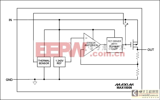
Figure 4. This automotive linear regulator requires a minimum number of pins and external components, minimal board space, and a minimum (typical) no-load supply current of 9.5μA.
Power-Dissipation Problems
To save board space and cost, designers sometimes avoid the use of a switch-mode power supply, even when the application is pushing the linear regulator to the edge of its power-dissipation capability. Consider, for example, an automotive electrical control unit (ECU) that requires a 5V supply voltage. The ECU normally includes a microcontroller, a sensor, and
模拟电路 模拟芯片 德州仪器 放大器 ADI 模拟电子 相关文章:
- 12位串行A/D转换器MAX187的应用(10-06)
- AGC中频放大器设计(下)(10-07)
- 低功耗、3V工作电压、精度0.05% 的A/D变换器(10-09)
- PIC16C5X单片机睡眠状态的键唤醒方法(11-16)
- 用简化方法对高可用性系统中的电源进行数字化管理(10-02)
- 利用GM6801实现智能快速充电器设计(11-20)