再生的DS1847/DS1848电阻校准常数-Regener
时间:04-13
来源:互联网
点击:
| -050 version | -010 version | |||
| Constants | R0 (50kΩ) | R1 (10kΩ) | R0 (10kΩ) | R1 (10kΩ) |
| α | 3.78964 | 19.74866 | 8.4117 | 8.4117 |
| w | 1.265E-6 | 7.875E-6 | 7.345E-6 | 7.814E-6 |
| z | 5.808E-7 | 7.5E-7 | 506.7E-9 | 523.5E-9 |
Using the constants in Table 1 along with the values from the measurements, Equations 1 through 8 yield the remainder of the real values of the calibration constants y, x, v, and u. These equations must be worked in the order provided since the values calculated initially are used in the subsequent equations. The real values can then be converted into their integer equivalents by dividing by their LSB weights, yielding Y, X, V, U, W, and Z.
Calculate:
Equation 1

Equation 2

Equation 3

Equation 4

Equation 5

Equation 6

Equation 7

Equation 8

Convert real values into hexadecimal integers:
Y = y / 10-7 = (dec)(hex) for resistor R0
Y = y / 10-7 = (dec)(hex) for resistor R1
X = x / 2-8 = (dec)(hex) for resistor R0
X = x / 2-8 = (dec)(hex) for resistor R1
V = v / 10-6 = (dec)(hex) for resistor R0
V = v / 10-6 = (dec)(hex) for resistor R1
U = u / 10-8 = (dec)(hex) for resistor R0
U = u / 10-8 = (dec)(hex) for resistor R1
W = w / 10-9 = 1.265E-6 / 10-9 = 1265(dec) = 04F1(hex) for resistor R0
W = w / 10-9 = 7.875E-6 / 10-9 = 7875(dec) = 1EC3(hex) for resistor R1
Z = z / 10-10 = 5.808E-7 / 10-10 = 5808(dec) = 16B0(hex) for resistor R0
Z = z / 10-10 = 7.5E-7 / 10-10 = 7500(dec) = 1D4C(hex) for resistor R1
Write to DS1847/48:
Once U, V, W, X, Y, and Z are calculated for each resistor (in hex), the values can be written into the corresponding locations of the corresponding LUTs in the location that the original factory calibration constants were originally (stated in the data sheet). Resistor 0 calibration constants are stored in Table 1 and Resistor 1 constants are stored in Table 2. For the DS1848, back-ups of both sets of calibration constants are stored in Table 0. Otherwise, one may wish to keep the calibration constants in real form so they can be used in the customer's calculations to program the entire LUTs.
Spreadsheet Calculator
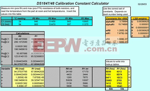
The accompanying spreadsheet calculator greatly simplifies calculation of the calibration constants (see Figure 1). Simply fill in the table with the measurements, and the calibration constants are instantly calculated, outputting both the real and integer values. Just be sure that the correct constants (α , w, and z) are used depending on the dash version. The hex values can then be written into the device so that it looks like it just came from the factory. Or, the real values can be used in additional calculations to implement the transfer function and reprogram the LUTs.
Figure 1. Example DS1847/48 calibration constant calculator.
Conclusion
This application note describes the measurements and calculations required to regenerate the DS1847/48 calibration constants for the rare occasion that the DS1847/48 needs to be put back into its factory programmed state. Once the measurements are made, the accompanying example spreadsheet can be used to calculate the calibration constants in both real and integer formats so that the DS1847/48 can be reprogrammed to resemble a virgin part, or the real values can be kept in the spreadsheet and incorporated into the customer's calculations to generate their LUTs.模拟电路 模拟芯片 德州仪器 放大器 ADI 模拟电子 相关文章:
- 12位串行A/D转换器MAX187的应用(10-06)
- AGC中频放大器设计(下)(10-07)
- 低功耗、3V工作电压、精度0.05% 的A/D变换器(10-09)
- PIC16C5X单片机睡眠状态的键唤醒方法(11-16)
- 用简化方法对高可用性系统中的电源进行数字化管理(10-02)
- 利用GM6801实现智能快速充电器设计(11-20)
