话音和DAC
时间:04-22
来源:互联网
点击:
This application note discusses the advantages of using these devices in these applications and provides an overview of the biasing circuit requirements in laser drivers.
Several families of laser drivers from a variety of vendors are designed to use resistors to control the modulation and bias currents supplied by the laser driver. Potentiometers and digital-to-analog converters (DACs) can also be used to control these parameters. With each control method, there are benefits and tradeoffs that will affect the overall laser driver's performance. To fully understand the advantages and disadvantages of the choices of laser driver control systems, some familiarity with laser drivers and fiber module design is essential.
Originally, resistors were used to control modulation and bias currents, as shown on many laser driver data sheets. While the least expensive component option, resistors don't allow real-time adjustments and tweaking them during the system calibration manufacturing step is difficult and time consuming. A better solution is to use a mechanical potentiometer (variable resistor), which allows manual adjustment.
As volumes increase and automation becomes important, the mechanical potentiometers can be replaced by digital potentiometers. Digital potentiometers also offer active digital control.
Active digital control is a technique of monitoring a parameter (such as output power) by measuring it with an ADC, processing it with a digital engine, and then using this information to adjust a parameter (such as laser driver output current). Active digital engines can compensate for the temperature dependence of laser diodes.
DACs can be used in most places that a potentiometer can be used, and can offer several advantages in some designs.

Figure 1. Laser driver internal architecture for sensing the value of the programming resistor.

Figure 2. Programming a laser driver with a digital potentiometer.
However, the resistance value of the available pots may not precisely line up with the desired range of programming current. Additional resistors can be used to more directly map the range of the pot onto the range of the currents desired (see Figure 3). Note that the current varies with the inverse of the resistance. Digital potentiometers usually have evenly spaced steps, which means that the resulting step size of the programming current will be large in the low resistance range of the pot, and small in the high resistance range.

Figure 3. Programming a laser driver current with an optimized programming range potentiometer.

Figure 4. Programming a laser driver current with a DAC.
Some of the reasons a design engineer would consider using a DAC include:
Several families of laser drivers from a variety of vendors are designed to use resistors to control the modulation and bias currents supplied by the laser driver. Potentiometers and digital-to-analog converters (DACs) can also be used to control these parameters. With each control method, there are benefits and tradeoffs that will affect the overall laser driver's performance. To fully understand the advantages and disadvantages of the choices of laser driver control systems, some familiarity with laser drivers and fiber module design is essential.
Originally, resistors were used to control modulation and bias currents, as shown on many laser driver data sheets. While the least expensive component option, resistors don't allow real-time adjustments and tweaking them during the system calibration manufacturing step is difficult and time consuming. A better solution is to use a mechanical potentiometer (variable resistor), which allows manual adjustment.
As volumes increase and automation becomes important, the mechanical potentiometers can be replaced by digital potentiometers. Digital potentiometers also offer active digital control.
Active digital control is a technique of monitoring a parameter (such as output power) by measuring it with an ADC, processing it with a digital engine, and then using this information to adjust a parameter (such as laser driver output current). Active digital engines can compensate for the temperature dependence of laser diodes.
DACs can be used in most places that a potentiometer can be used, and can offer several advantages in some designs.
The Control Section of a Laser Driver
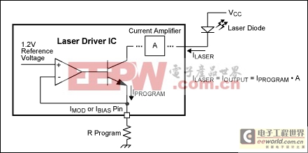
Many laser drivers have a very simple structure that translates the programming resistance (RPROGRAM) into the output bias and modulation depth currents (see Figure 1). Typically, the internal circuitry behind the laser driver current control pins (i.e., IMOD, IBIAS) includes an internal reference voltage source. The output current of this internal voltage source is measured, and amplified via a current amplifier, the output of which is the output of the laser driver. A simple resistor connected between ground and these control pins, provides a consistent control current for that circuit. Note that the laser driver only cares about the amount of current pulled out of this pin, not the value of the resistor connected to it. Hence, the resistor can be replaced by a DAC that controls this current, as will be described later. Typically, the gain of the current amplifier is on the order of 100-200 (mA/mA), and typical output currents are up to 50-80mA.
Figure 1. Laser driver internal architecture for sensing the value of the programming resistor.
Digital Pot Options (and Advantages)
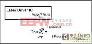
Using a digital pot in place of the control resistor is the simplest and most obvious approach (see Figure 2).
Figure 2. Programming a laser driver with a digital potentiometer.
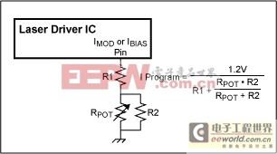
However, the resistance value of the available pots may not precisely line up with the desired range of programming current. Additional resistors can be used to more directly map the range of the pot onto the range of the currents desired (see Figure 3). Note that the current varies with the inverse of the resistance. Digital potentiometers usually have evenly spaced steps, which means that the resulting step size of the programming current will be large in the low resistance range of the pot, and small in the high resistance range.

Figure 3. Programming a laser driver current with an optimized programming range potentiometer.
DAC Options (and Advantages)
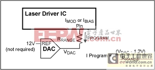
A DAC can be used in place of a pot to control the laser driver currents. A voltage output DAC is used with a series resistor, such that the current drawn from the laser driver control pin is the programming current (see Figure 4). The ideal full scale/reference voltage for the DAC is the same as reference voltage internal to the particular laser driver. It can be larger, but the usable range of the DAC is compromised
Figure 4. Programming a laser driver current with a DAC.
Some of the reasons a design engineer would consider using a DAC include:
模拟电路 模拟芯片 德州仪器 放大器 ADI 模拟电子 相关文章:
- 12位串行A/D转换器MAX187的应用(10-06)
- AGC中频放大器设计(下)(10-07)
- 低功耗、3V工作电压、精度0.05% 的A/D变换器(10-09)
- PIC16C5X单片机睡眠状态的键唤醒方法(11-16)
- 用简化方法对高可用性系统中的电源进行数字化管理(10-02)
- 利用GM6801实现智能快速充电器设计(11-20)
