介绍DS1847用于工业控制-Introduction of
时间:05-27
来源:互联网
点击:
Abstract: This application note introduces the DS1847 and DS1848, dual digital temperature-controlled variable resistors, to the industrial controls market. By temperature compensating the resistors, the resistors can either remain at a specific resistance or vary over temperature by programming a unique resistor value every 2°C. The DS1847 can also be used to control voltage or current. The DS1847 and DS1848 are identical except the DS1848 includes additional user programmable EEPROM. In this application note, DS1847 will refer to the DS1847 and DS1848.
This application note presents the DS1847 features and operation in addition to some application ideas. To discuss how the DS1847 can benefit your application, please contact Applications Support atMixedSignal.Apps@dalsemi.com MixedSignal.Apps@dalsemi.com.
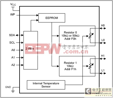
Figure 1. Block diagram.
The DS1847 can operate standalone in closed loop mode without a microcontroller or with a microcontroller using an optional 2-wire master. The 2-wire master allows multiple devices to be controlled in different locations.
Figure 2 shows how multiple DS1847s can be connected to a 2-wire master. The address pins allow up to 8 devices on the 2-wire bus.
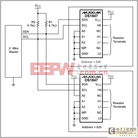
Figure 2. 2-Wire interface.
With the ability to program the resistance as a function of temperature, the user can create a very low tempco resistor. The compensated tempco error is ±4 LSB. A transfer function can be programmed into the resistor lookup table (LUT) to fit many applications. The resistor LUT is EEPROM memory that can contain a unique resistor value at a specific temperature from -40°C to +95°C in 2°C increments. See the DS1847 Operation section for more information on the LUT.
The resistor outputs can also be used as digital outputs to drive external circuitry. The outputs can be used as alarms or as general-purpose digital outputs. The DS1847 can be configured to output a resistance, voltage, or current.
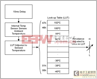
Figure 3. Lookup table.
Figure 4 shows how the DS1847 can be connected to a fixed resistor to create a voltage divider (Vout0). This will provide a fixed or variable output voltage to an application over temperature. A transfer function can be programmed into the LUT to change the voltage with temperature.
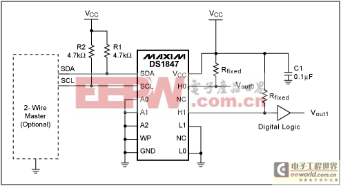
Figure 4. Voltage and digital outputs.
The DS1847 can also be configured to create a digital output (Vout1). Using a fixed resistance of 4.7kΩ and the 50kΩ variable resistor, the output voltage range is 0.77V to 4.57V (see Example 1). The digital output can be used as an alarm or warning when the temperature reaches a certain value (see the Voltage Alarm Example). The digital output can be set to go low or high if the temperature changes from the set value or if the temperature exceeds a certain value.
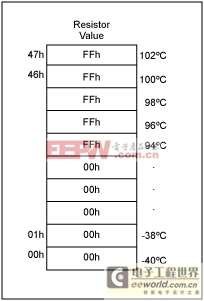
Figure 5. Lookup table for a voltage alarm.
Example 1.
If the DS1847 will be configured as a digital output, the output voltage needs to meet the VIH and VIL levels of the digital circuitry. Equation 1 shows how to calculate the output voltage at a certain fixed resistance.
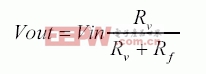
Equation 1
Where, Vin = Vcc = 5V
This application note presents the DS1847 features and operation in addition to some application ideas. To discuss how the DS1847 can benefit your application, please contact Applications Support atMixedSignal.Apps@dalsemi.com MixedSignal.Apps@dalsemi.com.
DS1847 Features
Figure 1 shows a block diagram of the DS1847. The DS1847 operates from a 3V or 5V supply over the temperature range of -40°C to +95°C and offers internal closed loop temperature compensation.Figure 1. Block diagram.
The DS1847 can operate standalone in closed loop mode without a microcontroller or with a microcontroller using an optional 2-wire master. The 2-wire master allows multiple devices to be controlled in different locations.
Figure 2 shows how multiple DS1847s can be connected to a 2-wire master. The address pins allow up to 8 devices on the 2-wire bus.
Figure 2. 2-Wire interface.
Temperature Compensation
One of the benefits of the DS1847 is the internal closed loop temperature compensation. Since the resistor settings and memory are nonvolatile, a microprocessor is not needed when using the DS1847.With the ability to program the resistance as a function of temperature, the user can create a very low tempco resistor. The compensated tempco error is ±4 LSB. A transfer function can be programmed into the resistor lookup table (LUT) to fit many applications. The resistor LUT is EEPROM memory that can contain a unique resistor value at a specific temperature from -40°C to +95°C in 2°C increments. See the DS1847 Operation section for more information on the LUT.
The resistor outputs can also be used as digital outputs to drive external circuitry. The outputs can be used as alarms or as general-purpose digital outputs. The DS1847 can be configured to output a resistance, voltage, or current.
DS1847 Operation
The DS1847 has a LUT that determines the resistor value at a specific temperature (see Figure 3). First, after a 10ms conversion time, the internal temperature sensor senses the ambient temperature. This temperature determines the LUT address. If the temperature sensed is -38°C, the corresponding address is 01h. The resistance value in address location 01h is used to adjust the resistance.Figure 3. Lookup table.
Using the DS1847 with Industrial Controls
The DS1847 can be beneficial in industrial control applications. First, the temperature-controlled resistor can provide a relatively constant resistance over temperature or the resistance can be set to increase or decrease with temperature.Figure 4 shows how the DS1847 can be connected to a fixed resistor to create a voltage divider (Vout0). This will provide a fixed or variable output voltage to an application over temperature. A transfer function can be programmed into the LUT to change the voltage with temperature.
Figure 4. Voltage and digital outputs.
The DS1847 can also be configured to create a digital output (Vout1). Using a fixed resistance of 4.7kΩ and the 50kΩ variable resistor, the output voltage range is 0.77V to 4.57V (see Example 1). The digital output can be used as an alarm or warning when the temperature reaches a certain value (see the Voltage Alarm Example). The digital output can be set to go low or high if the temperature changes from the set value or if the temperature exceeds a certain value.
Voltage Alarm Examples
To set the voltage to go high when a specific temperature is reached, 94°C in this illustration (see Figure 5), the LUT would be programmed to set the resistor to the minimum position (position 0) for the temperature range -40°C to 92°C. For temperatures 94°C and above the resistor position would be set to FFh.Figure 5. Lookup table for a voltage alarm.
Design Considerations
When using the DS1847 as a voltage divider or a digital output, the fixed resistor value needs to be calculated (see Figure 6).Example 1.
If the DS1847 will be configured as a digital output, the output voltage needs to meet the VIH and VIL levels of the digital circuitry. Equation 1 shows how to calculate the output voltage at a certain fixed resistance.
Equation 1
Where, Vin = Vcc = 5V
模拟电源 电源管理 模拟器件 模拟电子 模拟 模拟电路 模拟芯片 德州仪器 放大器 ADI 相关文章:
- 采用数字电源还是模拟电源?(01-17)
- 模拟电源管理与数字电源管理(02-05)
- 数字电源正在超越模拟电源(03-19)
- 数字电源PK模拟电源(04-03)
- TI工程师现身说法:采用数字电源还是模拟电源?(10-10)
- 开关电源与模拟电源的分别(05-08)