过电压保护汽车系统-Overvoltage Protecti
时间:05-27
来源:互联网
点击:
Note: The reverse-leakage current measured from -40°C to 60°C was effectively zero (infinite-leakage resistance).
The forward voltage drop of the protection circuit in Figure 2 was measured at three supply voltages—4.5V, 5V, and 5.5V—for temperatures in the -40°C to 125°C range. The results obtained are presented in the graph in Figure 4.
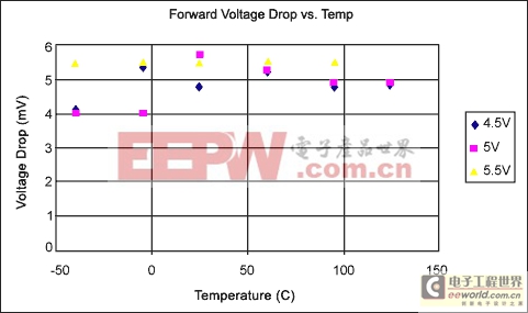
Figure 4. Forward voltage drop versus temperature for the circuit in Figure 2.
Examining the results in Figure 4 shows the forward voltage drop of the circuit in Figure 2 to be below 6mV for temperatures in the -40°C to 125°C range. The effect of power-supply voltage drops on ratiometric measurement errors is the same as with any other system offsets, so long as the circuit has been calibrated with the protection circuit in place. When subjected to a 10% change in power-supply voltage, the error induced by any offset within the system will be 10% of the offset value. So, a 6mV offset (voltage drop) will induce a ratiometric measurement error of 0.6mV when the power supply is changed by 10%. In a system where the output SPAN is set to 4V, this 0.6mV error will correspond to a measurement error of 0.015% of SPAN.
Less Expensive Reverse-Voltage Protection
The circuit in Figure 2 uses a p-channel MOSFET as the reverse-voltage protection element. This has the advantage of disconnecting the load during reverse-voltage events and therefore places no particular requirements on the power supply. A less expensive alternative to this is to use a simple diode connected across the power supply as the reverse protection element. This arrangement is shown in Figure 5, but can be used only where the main system power supply is current-limited or fused. The diode protects the circuit by conducting whenever a reverse voltage is applied to the power-supply inputs of the circuit. The diode must be rated to withstand the maximum current or the fuse rating of the system's power source.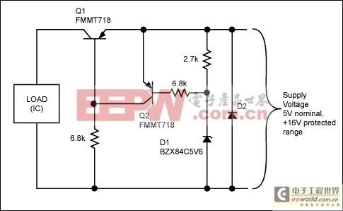
Figure 5. Use of a diode as the reverse-voltage protection element.
Full Sensor Signal Conditioner Overvoltage/Reverse-Voltage
Protection Circuit
Figure 6 illustrates a fully protected, sensor signal conditioning circuit using the circuits described above with the MAX1452-MAX1455 signal conditioning ICs. The circuit shown in Figure 5 protects the main power supply to the MAX1455. Series resistors provide additional protection for the signal output pins. The series resistance values are selected so as not to exceed the maximum specified pin current into the IC, with a ±16V fault applied to the signal lines.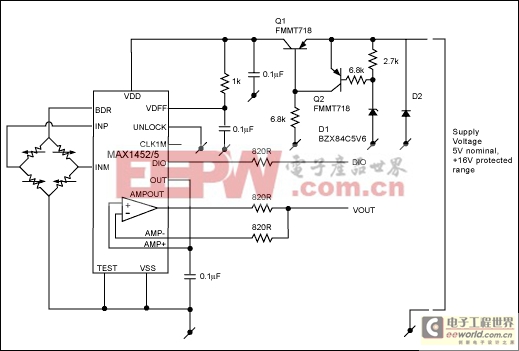
Figure 6. Fully protected, sensor signal conditioner circuit withstands the application of ±16V to any wiring connection.
模拟电源 电源管理 模拟器件 模拟电子 模拟 模拟电路 模拟芯片 德州仪器 放大器 ADI 相关文章:
- 采用数字电源还是模拟电源?(01-17)
- 模拟电源管理与数字电源管理(02-05)
- 数字电源正在超越模拟电源(03-19)
- 数字电源PK模拟电源(04-03)
- TI工程师现身说法:采用数字电源还是模拟电源?(10-10)
- 开关电源与模拟电源的分别(05-08)