监测集成电路监控电池供电设备
时间:01-30
来源:互联网
点击:
You can avoid false resets by choosing a supervisory circuit whose reset comparator has a propagation delay of 10μs to 30μs. Shorter propagation delays (of a few hundred nanoseconds) react quickly to VCC transients, and are therefore likely to generate false resets. Long delays, on the other hand, can allow VCC to fall too far outside the system IC's operating range before the processor is reset. The majority of 5V applications include sufficient capacitance to reduce the VCC fall rate such that a reset occurs before VCC falls below the minimum level specified in the IC's electrical characteristics.
Battery Backup
For critical systems that require non-volatile memory, the designer can choose either erasable/programmable memory or a CMOS RAM with backup battery. EEPROMs and flash memory are rated not only for memory capacity, but also for the number of write cycles they can undergo. The most common non-volatile memory includes a switch that connects the CMOS RAM to the lithium backup battery or VCC, whichever is higher.Large capacitors (around 0.5F) offer a popular method for providing a short-duration memory backup. Called SuperCaps? or MaxCaps?, these capacitors charge from VCC through a diode during normal operation (Figure 5). Charging current is limited by the capacitors' internal series resistance, which is relatively high. The RAM is switched from VCC to the capacitor when VCC collapses below the IC's reset threshold. The available backup time depends on the level of quiescent current into the RAM and supervisor IC, and the self-discharge leakage of the capacitor itself. For the many systems that draw only tens of microamps in backup mode, such backup capacitors can maintain the memory contents for several hours. The 1μA quiescent currents of Maxim supervisors, for instance, are generally insignificant.
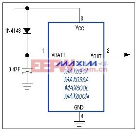
Figure 5. A very large capacitor (0.47F in this case) can serve as a backup battery in systems with low quiescent current.
Backup-battery switchover in 3V applications presents a challenge: How do you determine when to switch between a 3.3V VCC and a 3.6V lithium backup cell? One way is to define a ground-referenced voltage that is higher than the CMOS RAM's minimum standby voltage. Thus, VCC supplies the RAM until it falls to slightly more than 2V; RAM is then switched to the backup battery (Figure 6).

Figure 6. When VCC sinks to slightly above 2V, this system switches the CMOS RAM from VCC to the backup battery.
Special Cases
To conserve battery energy, designers of battery-operated portable equipment often make use of the 80CL51 μC's power-down mode. If the preservation of CMOS memory content is critical, IC1's active-low LOWLINE output (Figure 6) generates an interrupt. This interrupt signal can trigger a shutdown routine when the main battery voltage goes low enough to cause VCC to fall out of tolerance. RAM contents are kept alive by whatever energy remains in the battery.With the μC in power-down mode and the supervisor's RESET connected directly to the μC's RST terminal, a VCC decline below the reset threshold will cause RESET to go high. This, in turn, wakes up the μC and places it in run mode, increasing its quiescent current from approximately 100μA to 6mA. Battery voltage continues to fall and VCC remains below the threshold, so 6mA will drain the battery, considerably shortening the available backup time.
Simply combining active-low LOWLINE and RESET with an AND gate (Figure 7) ensures that IC3's RST is driven high only for the reset timeout period (not when VCC is falling). In other words, RST goes high after VCC has been restored (by recharging the battery or installing a fresh one) and has recrossed the low-line threshold. The AND gate thus allows the sleeping controller to remain in a sleep state.
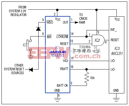
Figure 7. The AND gate preserves battery energy by preventing an unnecessary shift in microcontroller operation-from sleep mode to the higher-current idle mode.
With VCC in its normal operating range, RESET is low and active-low LOWLINE is high. When VCC falls below the low-line threshold (typically 45mV above the reset threshold), active-low LOWLINE goes low, signaling the 80CL51 to begin its shutdown routine. RESET asserts when VCC encounters the reset threshold, but active-low LOWLINE forces the AND-gate output to remain low.
On power-up active-low LOWLINE remains low, therefore RST remains low until VCC crosses the low-line threshold. RESET then propagates through to the RST terminal for the duration of the reset timeout period. As a result, the 80CL51 exits its sleep mode only when VCC is valid.
Also desirable in this application is an ability to detect whether the battery has discharged below the safe RAM-backup voltage at any time during the sleep period. Using this information, the system decides whether to perform a "warm boot" based on the contents of the RAM, or a "cold boot" that starts from scratch because low battery voltage may have corrupted the RAM data. IC1's BATT terminal (pin 16) tells the μC which boot is appropriate.
IC1 has a low-battery comparator that normally indicates the state of a backup battery connected to its BATT terminal. This comparator output (BATT OK) is not latched. The application of Figure 7 has no backup battery, so you can use BATT to latch the state of BATT OK. Simply connect BATT to an available I/O pin on the 80CL51, and to the BATT OK terminal via a 10kΩ resistor.
To set up for normal operation, the μC pulses the I/O line high for about 30μs, then configures the line as a high-impedance input. The comparator in IC1 drives BATT OK high, which pulls BATT high and latches it in that condition. The comparator is powered by VCC, so its output in the high state is near VCC. If VCC goes as low as 2.25V at any time during the sleep period, the comparator output snaps low and pulls BATT low, latching it in the low condition. After VCC is restored (by recharging the main battery or replacing it) the μC polls BATT before proceeding: high indicates a warm boot, and low indicates a cold boot.
μCs such as the Motorola 68HC11 have bidirectional reset pins that may contend with active-low RESET from the supervisory IC. If the supervisor reset is high, for instance, and the μC tries to pull it low, the result may be an indeterminate logic level. Figure 8 connections allow both the supervisor and μC to assert valid resets to the system, and also ensure sufficient duration for the reset pulses (μC resets may be too short for some devices in the system).
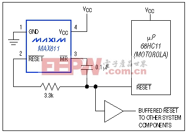
Figure 8. These connections allow dual control of the buffered reset line, and extend the duration of resets issued by the μP.
The capacitor enables resets from the supervisor and μC to pull active-low MR low. active-low MR going low initiates a 200ms timeout within the supervisor, producing a 200ms minimum pulse at its active-low RESET terminal (pin 2) that overrides the μC active-low RESET and drives the system reset line via the buffer. active-low MR returns high as the capacitor charges. When the μC active-low RESET de-asserts following the timeout delay, the capacitor discharges through the active-low MR pull-up resistor and an internal ESD-protection diode.
- 网络环境下的蓄电池智能监测系统设计(01-06)
- 阀控铅酸蓄电池的失效探讨及在线监测(01-06)
- 单片机嵌入式系统在运程电网监测系统中的应用(05-13)
- 蓄电池监测装置的研究(05-19)
- 高压开关触头温度实时无线监测系统的设计与实现(09-18)
- 利用高性能同时采样ADC降低高级电力线监测系统的成本(12-01)