选择最佳测试音和测试设备的成功高速ADC正弦波
时间:06-19
来源:互联网
点击:
Probably the most critical elements in such a test setup (Figure 1) are the synthesized signal generators, used to generate the waveforms for the clock and input frequencies. Suitable signal generators must feature low phase noise; because measured dynamic parameters such as SNR will degrade dramatically with an increase in phase noise "Defining and Testing Dynamic Parameters in High-Speed ADCs, Part 1". Furthermore, these signal synthesizers have to provide adequate output power, must have phase locking capabilities, and a frequency resolution of 0.1Hz or better to ensure accurate coherence.
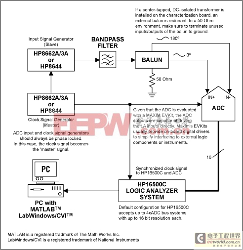
Figure 1.
Although generators such as the HP8662A series from Hewlett-Packard/Agilent are rather expensive and have a limited output amplitude range of -139dBm to +13dBm (0.025μVRMS to 1VRMS into a 50Ω load), they satisfy all other test requirements and are most suitable for the dynamic tests of high-speed converters.
To further reduce the harmonic distortion components of the synthesizer's output frequency it is recommended to filter the desired test tone by applying a high-quality bandpass between generator and ADC input drive.
Clock and signal inputs of fast ADCs usually are equipped with true differential input architectures, which require the signal generator's single-ended output to be converted to a differential signal. This can be achieved by using an external balun or an off-the-shelf transformer with center tap and DC isolation. Usually, the latter is a surface-mount component and should be incorporated on the characterization board, used to test the ADC. Most of Maxim's high-speed data converter evaluation kits feature such transformers and emphasize on impedance matched I/O lines to keep unwanted signal skew and phase mismatch at a minimum.
To capture digital data on the parallel output ports of a high-speed ADC a fast Logic Analyzer will be needed. An excellent choice is the Hewlett-Packard/Agilent HP16500 Logic Analyzer mainframe. For converter sampling/clock speeds greater than 100MHz, this system accepts high-speed data capture cards such as the HP16517A. The system's mainframe features a GPIB/HPIB bus, capable of interfacing with a PC-based GPIB to transmit data from the Logic Analyzer to a PC quickly. One may of course use the floppy drive built into the instrument to store data, however depending on the size of the data record (number of points in the FFT) this may take significantly longer than just utilizing the analyzer's GPIB interface. Once data has been sent to the PC, a signal processing software such as MATLAB may be used to analyze the data records from the logic analyzer. The following MATLAB sample code maybe used to calculate the basic AC specifications of any a high-speed ADC.
%Source Code Sample MAX144X Family | ||||
| %The following program code plots the FFT spectrum of a desired test tone. Test tone based on coherent sampling criteria, and | ||||
| %computes SNR, SINAD, THD and SFDR. | ||||
| %Copyright Au/Hofner, Maxim Integrated Products, 120 San Gabriel Drive, Sunnyvale, CA94086 | ||||
| %This program is believed to be accurate and reliable. This program may get altered without prior notification.; | ||||
| disp('HP16500C LA 100/110 State Card'); | ||||
| filename=input('Enter file name or press RETURN to accept data from LA via GPIB/HPIB): '); | ||||
| if isempty(filename) | ||||
| filename = 'listing'; | ||||
| end | ||||
| fid=fopen(filename,'r'); | ||||
| numpt=input('Number of Points in FFT? '); | ||||
| fclk=input('Sampling Frequency (MHz)? '); | ||||
| numbit=input('ADC Resolution? '); | ||||
| %Discard first 13 lines of the LA listing (LA header), as they don't contain valid data. | ||||
| for i=1:13, | ||||
| fgetl(fid); | ||||
| end | ||||
| [v1,count]=fscanf(fid,'%f',[2,numpt]); | ||||
- ADC前端电路的五个设计步骤(04-27)
- 消除测试设备对射频器件测量影响(02-27)
- 用差分放大器来驱动高速ADC(03-28)
- 一种用于高速ADC的采样保持电源电路的设计(10-21)
- 高速ADC电源设计方案(08-28)
- 基于高速ADC的脉冲测量(12-08)