如何应用AndesCore EDM安全访问机制
时间:01-30
来源:互联网
点击:
作者:沈永胜,技术副哩,晶心科技股份有限公司
EDM安全存取是AndesCoreTM内建的功能(option),应用在安全存取的控管。EDM安全存取有二种的控管方式:debug access indication和EDM access restriction。第一种控管方式(debug access indication)提供了一个sideband signal用于指示从调试器(Debug host)的请求。第二种控管方式, 控制AndesCoreTM的input port(edm_restrict_access )达到EDM存取的限制。更详细的内容在后续章节会有更深入的介绍。
1. EDM功能介绍
一个debug system包含一个debug host和一个target system。EDM主要的功能就是translate debug host发出的TAP指令来存取系统memory或是CPU。下图为基本的debug系统方块图。
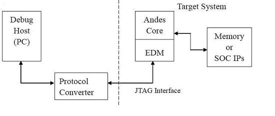
图表1 基本的debug系统方块图
下图说明TAP 指令的种类
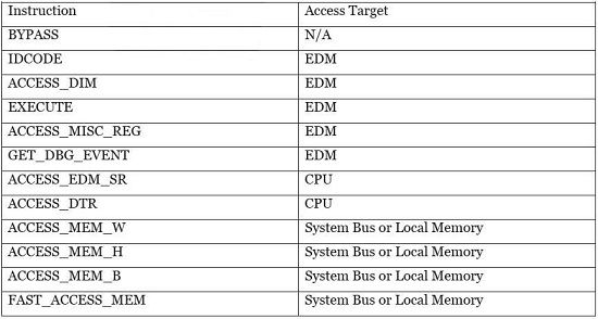
图表2 TAP 指令的种类
2. 控制EDM存取的限制
使用EDM的访问方式会被一个sideband signal (edm_restrict_access) 所影响。当这个signal值是high,仅仅只能对EDM MISC registers做读取的动作。而想要存取CPU/System Bus/Local Memory的动作将会被封锁住并且会得到下面的结果:
读为零写忽略
不正确的JTAG instruction(JTAG ICE debugger会timeout)
下图说明EDM限制存取方块图。
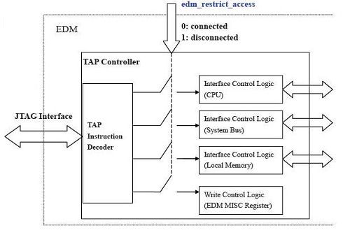
图表3 EDM限制存取方块图
在启用存取限制功能后,下图说明出每个TAP指令的行为。
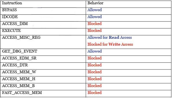
图表4 在启用存取限制功能后,下图说明出每个TAP指令的行为
如何实现EDM存取限制,在系统设计上有很多种实现方法,以控制edm restrict access的signal。两种基本的设计方案说明如下:
eFUSE方式使用Chip重新编程管理控制
SOC方式使用软件管理控制
hardware实现控制edm_restrict_access的示意图如下:
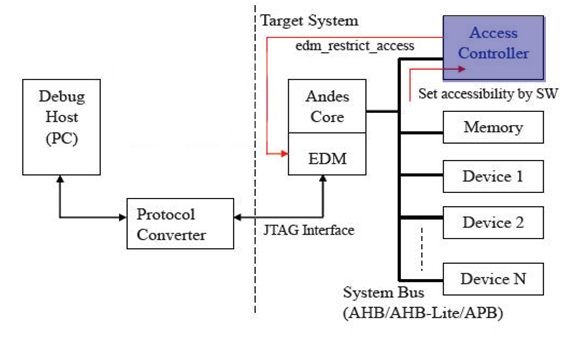
图表5 hardware实现控制edm_restrict_access的示意图
software实现控制edm_restrict_access的例子如下:
sethi $r2,#0x80000
ori $r2,$r2,#0x8c
sethi $r3,#0x04030
ori $r3,$r3,#0x201
swi $r3,[$r2+#0]
3. EDM 存取指示
AndesCoreTM增加一个额外的sideband signal,xdebug_access(active-high),根据此sideband signal来决定request的host是否为EDM。而device就能根据此sideband signal决定是否要把request的data内容传回到host。
sideband signal的名称根据bus interface的类型而有所不同。对于AndesCoreTM处理器,基本的信号名称如下所示:
AHB/AHB-Lite => hdebug_access
APB => pdebug_access
EILM => eilm_debug_access
EDLM => edlm_debug_access
3.1.debug存取识别信号控制
当debug exception发生后,CPU将进入debug mode。然后CPU将会留在debug access mode直到CPU执行到IRET instruction并且trusted_debug_exit 是处于high后CPU将离开debug access mode,反之trusted_debug_exit如果是low,CPU将会保留在debug access mode。
实现控制trusted_debug_exit信号,有二种可供选择的方式如下:
trusted_debug_exit信号总是给high
增加一个权限管理逻辑去控制trusted_debug_exit信号是high或是low权限管理逻辑方块图如下所示:
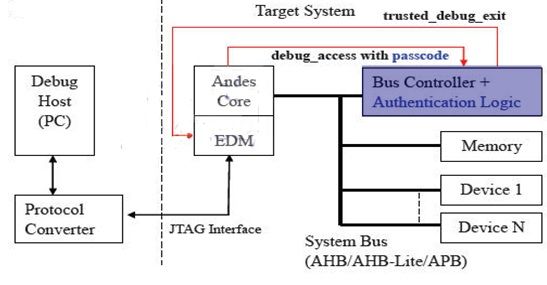
图表6 权限管理逻辑方块图
如何控制trusted_debug_exit信号时序图如下所示:
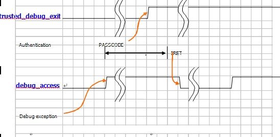
图表7 如何控制trusted_debug_exit信号时序图
如下例子说明了如何产生trusted_debug_exit控制信号的verilog code:
The code example (Verilog) of trusted_debug_exit generation is described below:
//
//--- Utilize passcode to generate trusted_debug_exit in AHB Bus Controller
//* assume zero-wait-state AHB access
…
parameter AUTH_CODE = 32’h0a0b0c0d;
...
always @(posedge hclk or negedge hreset_n) begin
if (!hreset_n) begin
passcode_reg <= 32'd0;
end
else if (passcode_wen) begin //debugger enters passcode through debug access
passcode_reg <= hwdata[31:0];
end
end
…
//validate passcode to generate trusted_debug_exit
assign trusted_debug_exit = (passcode_reg == AUTH_CODE);
3.2.debug存取指示应用
下图说明AHB bus如何使用hdebug_access和验证逻辑来防止恶意的debug存取
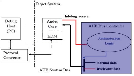
图表8 AHB bus如何使用hdebug_access和验证逻辑来防止恶意的debug存取
如下verilog code说明了如何使用hdebug_access信号:
//--- Use hdebug_access to prevent malicious debug access in AHB Bus Controller
//* assume zero-wait-state AHB access
…
parameter IRRELEVANT_DATA = 32’hcafe0001;
parameter AUTH_CODE = 32’h01020304;
…
always @(posedge hclk or negedge hreset_n) begin
if (!hreset_n) begin
dbg_acc_d1 <= 1'b0;
end
else begin // data phase indication of debug access
dbg_acc_d1 <= hdebug_access;
end
end
...
always @(posedge hclk or negedge hreset_n) begin
if (!hreset_n) begin
passcode_reg <= 32'd0;
end
else if (passcode_wen) begin //debugger enters passcode through debug access
passcode_reg <= hwdata[31:0];
end
end
…
//validate passcode to check authentication
assign auth_check_fail = (passcode_reg != AUTH_CODE);
//return irrelevant data if the authentication check of debug access fails
assign hrdata_out = {32{data_read_en}} &
((dbg_acc_d1 & auth_check_fail) IRRELEVANT_DATA : normal_data_out);
EDM安全存取是AndesCoreTM内建的功能(option),应用在安全存取的控管。EDM安全存取有二种的控管方式:debug access indication和EDM access restriction。第一种控管方式(debug access indication)提供了一个sideband signal用于指示从调试器(Debug host)的请求。第二种控管方式, 控制AndesCoreTM的input port(edm_restrict_access )达到EDM存取的限制。更详细的内容在后续章节会有更深入的介绍。
1. EDM功能介绍
一个debug system包含一个debug host和一个target system。EDM主要的功能就是translate debug host发出的TAP指令来存取系统memory或是CPU。下图为基本的debug系统方块图。

图表1 基本的debug系统方块图
下图说明TAP 指令的种类

图表2 TAP 指令的种类
2. 控制EDM存取的限制
使用EDM的访问方式会被一个sideband signal (edm_restrict_access) 所影响。当这个signal值是high,仅仅只能对EDM MISC registers做读取的动作。而想要存取CPU/System Bus/Local Memory的动作将会被封锁住并且会得到下面的结果:
读为零写忽略
不正确的JTAG instruction(JTAG ICE debugger会timeout)
下图说明EDM限制存取方块图。

图表3 EDM限制存取方块图
在启用存取限制功能后,下图说明出每个TAP指令的行为。

图表4 在启用存取限制功能后,下图说明出每个TAP指令的行为
如何实现EDM存取限制,在系统设计上有很多种实现方法,以控制edm restrict access的signal。两种基本的设计方案说明如下:
eFUSE方式使用Chip重新编程管理控制
SOC方式使用软件管理控制
hardware实现控制edm_restrict_access的示意图如下:

图表5 hardware实现控制edm_restrict_access的示意图
software实现控制edm_restrict_access的例子如下:
sethi $r2,#0x80000
ori $r2,$r2,#0x8c
sethi $r3,#0x04030
ori $r3,$r3,#0x201
swi $r3,[$r2+#0]
3. EDM 存取指示
AndesCoreTM增加一个额外的sideband signal,xdebug_access(active-high),根据此sideband signal来决定request的host是否为EDM。而device就能根据此sideband signal决定是否要把request的data内容传回到host。
sideband signal的名称根据bus interface的类型而有所不同。对于AndesCoreTM处理器,基本的信号名称如下所示:
AHB/AHB-Lite => hdebug_access
APB => pdebug_access
EILM => eilm_debug_access
EDLM => edlm_debug_access
3.1.debug存取识别信号控制
当debug exception发生后,CPU将进入debug mode。然后CPU将会留在debug access mode直到CPU执行到IRET instruction并且trusted_debug_exit 是处于high后CPU将离开debug access mode,反之trusted_debug_exit如果是low,CPU将会保留在debug access mode。
实现控制trusted_debug_exit信号,有二种可供选择的方式如下:
trusted_debug_exit信号总是给high
增加一个权限管理逻辑去控制trusted_debug_exit信号是high或是low权限管理逻辑方块图如下所示:

图表6 权限管理逻辑方块图
如何控制trusted_debug_exit信号时序图如下所示:

图表7 如何控制trusted_debug_exit信号时序图
如下例子说明了如何产生trusted_debug_exit控制信号的verilog code:
The code example (Verilog) of trusted_debug_exit generation is described below:
//
//--- Utilize passcode to generate trusted_debug_exit in AHB Bus Controller
//* assume zero-wait-state AHB access
…
parameter AUTH_CODE = 32’h0a0b0c0d;
...
always @(posedge hclk or negedge hreset_n) begin
if (!hreset_n) begin
passcode_reg <= 32'd0;
end
else if (passcode_wen) begin //debugger enters passcode through debug access
passcode_reg <= hwdata[31:0];
end
end
…
//validate passcode to generate trusted_debug_exit
assign trusted_debug_exit = (passcode_reg == AUTH_CODE);
3.2.debug存取指示应用
下图说明AHB bus如何使用hdebug_access和验证逻辑来防止恶意的debug存取

图表8 AHB bus如何使用hdebug_access和验证逻辑来防止恶意的debug存取
如下verilog code说明了如何使用hdebug_access信号:
//--- Use hdebug_access to prevent malicious debug access in AHB Bus Controller
//* assume zero-wait-state AHB access
…
parameter IRRELEVANT_DATA = 32’hcafe0001;
parameter AUTH_CODE = 32’h01020304;
…
always @(posedge hclk or negedge hreset_n) begin
if (!hreset_n) begin
dbg_acc_d1 <= 1'b0;
end
else begin // data phase indication of debug access
dbg_acc_d1 <= hdebug_access;
end
end
...
always @(posedge hclk or negedge hreset_n) begin
if (!hreset_n) begin
passcode_reg <= 32'd0;
end
else if (passcode_wen) begin //debugger enters passcode through debug access
passcode_reg <= hwdata[31:0];
end
end
…
//validate passcode to check authentication
assign auth_check_fail = (passcode_reg != AUTH_CODE);
//return irrelevant data if the authentication check of debug access fails
assign hrdata_out = {32{data_read_en}} &
((dbg_acc_d1 & auth_check_fail) IRRELEVANT_DATA : normal_data_out);
- 32位单精度浮点乘法器的FPGA实现(11-25)
- 再议嵌入式系统定义、特点及其学习要点(08-06)
- MCU&USB设备控制器IP核的设计(03-31)
- 双层AMBA总线设计及其在SoC芯片设计中的应用(06-07)
- TMS320C3X串口扩展技术(06-27)
- 基于RVM的层次化SoC芯片验证平台设计及应用(07-18)
