lpc54102例程(两种方案代码详解)
pute_Heartrate(void)
{
inti, N, Signal, runningTotal, current_sample = 0;
while(current_sample 《 SAMPLE_FREQUENCY/2){
Signal = temp_data[current_sample];
/* Keep track of time in milliseconds with sampleCounter variable */ sampleCounter = sampleCounter + 50;
/* Monitor the time since last beat to avoid noise */
N = sampleCounter - lastBeatTime;
/* Find the peak and trough of the pulse wave, avoid dichrotic noise by waiting 3/5 of last IBI */
if(Signal 《 thresh && N 》 (IBI/5)*3){
if (Signal 《 T){
/* Keep track of lowest point in pulse wave in the T variable */ T = Signal; } } /* Use threshold condition to filter out noise, store peak in P */ if(Signal 》 thresh && Signal 》 P){
P = Signal; } /* Analyze the data to find heartbeat */
f(N》500){
/* Avoid high frequency noise */
if((Signal》thresh)&&(Pulse==0)&&(N》(IBI/5)*3)){ Pulse=1; IBI=sampleCounter-lastBeatTime; lastBeatTime=sampleCounter; if(secondBeat){ secondBeat=0; for(i=0;i《=9;i++){ rate[i]=IBI; } } if(firstBeat){ firstBeat=0; secondBeat=1; continue; } /* Keep a running total of the last 10 IBI values */ runningTotal=0; for(i=0;i《=8;i++){ rate[i]=rate[i+1]; runningTotal += rate[i]; } /* Average the latest IBI values and calculate the BPM */ rate[9]=IBI; runningTotal+=rate[9]; runningTotal/=10; BPM=60000/runningTotal; QS=1; } }
/* Once the beat is over, reset values */
if (Signal 《 thresh && Pulse == 1){
Pulse = 0;
amp = P - T;
thresh = amp/2 + T;
P = thresh;
T = thresh; }
/* If we do not detect a heart beat in 2.5 seconds, reset all values */ if (N 》 2500){
thresh = 2548;
P = 2548;
T=2548; lastBeatTime= sampleCounter;
firstBeat = 1;
secondBeat = 0; } current_sample++; } }
lpc54102例程:二
LPCOpen_V2.14_LPC5410x的Peripheral例程
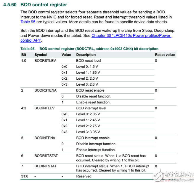
BOD是在设置了BOD中断电压水平(INTLEVEL),同时设置了重启电压水平(RSTLEVEL)之后,使能中断与重启,
源程序如下:
/* Set BOD detection interrupt to 3.05v and device reset to 1.5v */
Chip_PMU_SetBODLevels(PMU_BODRSTLVL_1_50V, PMU_BODINTVAL_3_05v);
/* Enable BOD reset and interrupt on low power level */
Chip_PMU_EnableBODReset();
Chip_PMU_EnableBODInt();
/* Enable BOD interrupt */
NVIC_EnableIRQ(BOD_IRQn);
为了方便观察BOD中断的运行,在中断中设置Board_LED_Toggle需要修改如下:
/* Brown-out detector interrupt */
void BOD_IRQHandler(void)
{
/* Turn on LED */
for(int i = 0; i 《 1000; i++) {
Board_LED_Toggle(1);
}
}
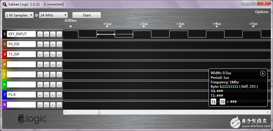
最终运行效果要求正常运行LED是熄灭的,而掉电过程中BOD中断使得LED闪亮,由于万利的板子是低电平点亮LED,因此在初始化阶段应该吧Board_LED_Set()的参数改为true,高电平之后LED熄灭。然后在BOD中断中可以blink闪亮。

运行效果可以通过拔掉供电电源(本人的为JLINK直接给板子供电,在jlink commander中输入Power off就可以)。此时LED会闪亮一下马上熄灭(断电)。
/**
* @brief PMU register block structure
* @note Most of the PMU support is handled by the PMU library.
*/
typedef struct {
__I uint32_t RESERVED0[4];
__I uint32_t RESERVED1[4];
__I uint32_t RESERVED2[4];
__I uint32_t RESERVED3[4];
__I uint32_t RESERVED4;
__IO uint32_t BODCTRL;
__I uint32_t RESERVED5;
__I uint32_t RESERVED6;
__IO uint32_t DPDWAKESRC;
} LPC_PMU_T;
#define LPC_PMU_BASE 0x4002C000UL
#define LPC_PMU ((LPC_PMU_T *) LPC_PMU_BASE)
(3)CLKOUT
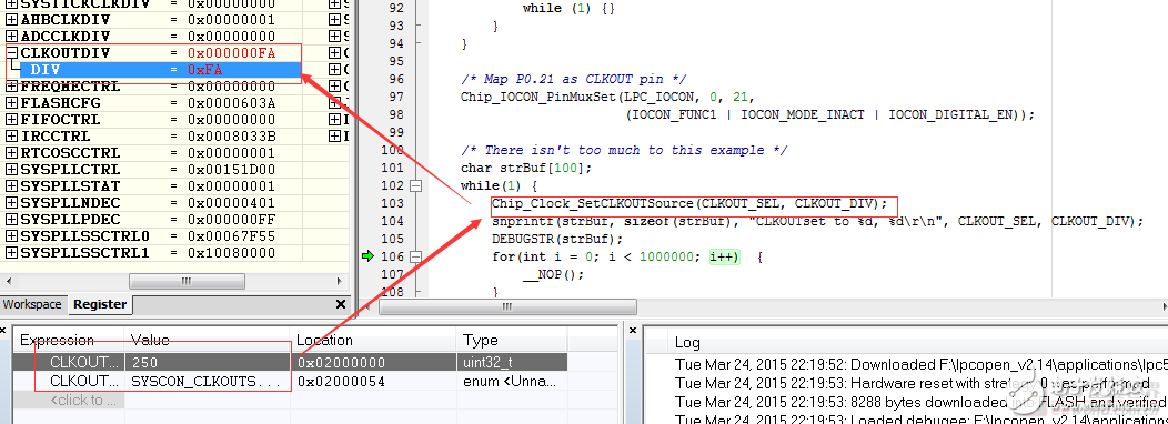
在P0.21(CLKOUT)引脚上可以测量如下时钟信号:
CLKOUT_div = 250

CPU被调试器暂停后,CLKOUT依然继续输出。
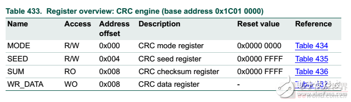
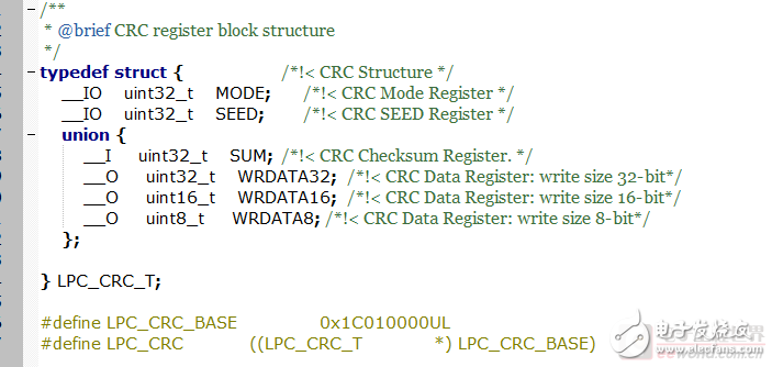
(4)CRC
CRC只需要运行例程即可。
CRC的功能定义和代码如下:
(5)IAP
lpc54102 相关文章:
- lpc54102引脚图_lpc54102引脚说明(09-20)
- lpc54102的特性(09-20)
- LT3751如何使高压电容器充电变得简单(08-12)
- 三路输出LED驱动器可驱动共阳极LED串(08-17)
- 浪涌抑制器IC简化了危险环境中电子设备的本质安全势垒设计(08-19)
- 严酷的汽车环境要求高性能电源转换(08-17)