how to get length of the input&output matching line?
时间:04-09
整理:3721RD
点击:
how to determine the length of the input and output matching line of the bandpass filter?izzit 1 wavelength?half wavelength? 1/4 wavelength? or others? for example, i need to design a bandpass filter with specification as below:
Center frequency: 2.4GHz
3dB bandwidth: 200MHz
dielectric constants: 4.5
dielectric thickness: 0.406mm
please refer to the picture below:
Center frequency: 2.4GHz
3dB bandwidth: 200MHz
dielectric constants: 4.5
dielectric thickness: 0.406mm
please refer to the picture below:
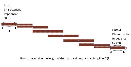
Theoretically, if are perfect 50 ohms, the length of these in/out transmission lines will not affect the characteristics of the filter.
When you design this filter, the widths and gaps of the resonators depend on what the input/output impedance is specified to be. IF you designed the filter impedance to be 50 ohms, then the above post is correct, the input and output 50 ohm lines can be any length you want.
In some cases you might deliberately design the coupled line filter for an impedance other than 50 ohms (for example if the gaps would be too small for a 50 ohm design). In those few cases, you would make the input and output lines quarterwave long, and their impedance would be Zm = √(50*Filter Impedance)
- Different Input/Output matching
- How do you choose input power while doing loadpull?
- Why an input inductor required in all GPS LNA?
- Input and output impedance matching in Distributed amplifier
- In distributed amplifiers, is it total input capacitance of the gain stage or Cgs
- curve fitting for input and output matching