pwm function
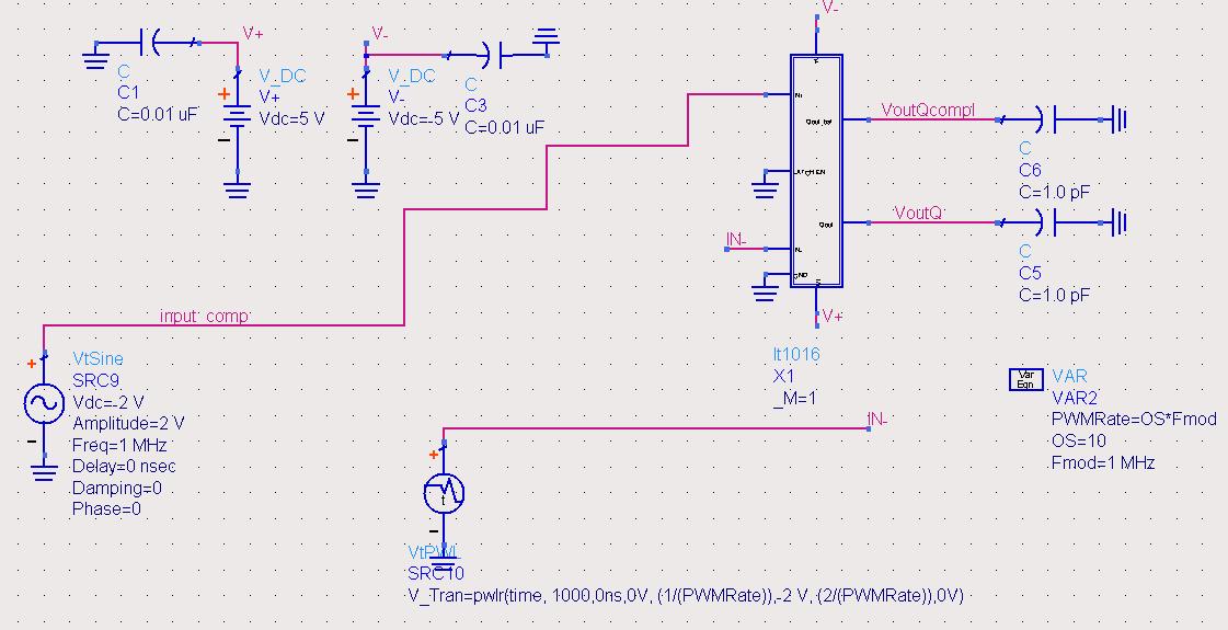
I m trying to generate a PWM signal at the output of the lt1016 comparator.
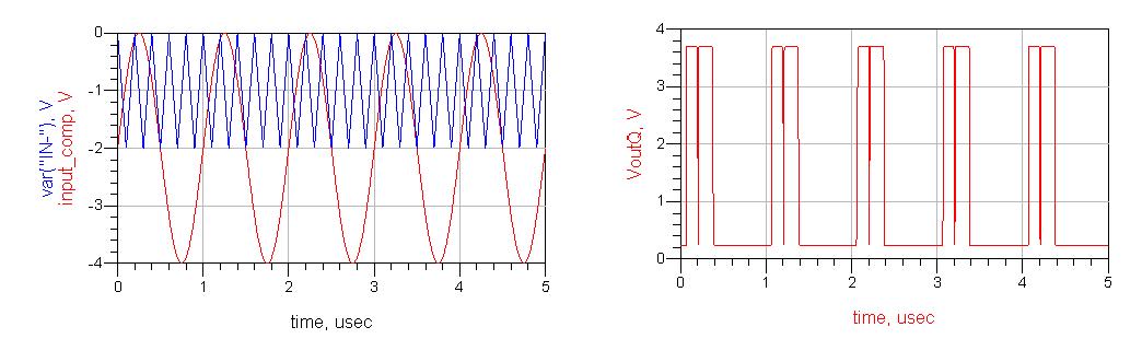
My idea is to compare a basic sinusoidal signal with a linear ramp signal aids of this comparator.
The linear ramp (called IN-) is plotted in blue.
I don't have idea to set up a correct linear ramp, what is the proper frequency the linear ramp should have?
Anybody?
Completely depends on then intended PWM purpose. Considering, that the post has been placen in RF, Microwave, Antennas and Optics forum, I don't have an idea. If you possibly intend reproduction of sine wave by the PWM, your example obviously indicates a too low PWM frequency. Why don't you simply try empirically?
Thank you.
Empirically? what do you mean?
I posted in "RF, Microwave, Antennas and Optics" because I want to do a fast PWM, i.e >1MHz.
But if a Moderator could move my post in a proper forum I will appreciate.
I need a PWM able to run with a 5 MHz (at the beginning I m using a 1 MHz signal). The comparator used is a very fast comparator, I guess able to follow a 5 MHz input signal...
I m trying to obtain a signal with a varying duty cycle according to the input voltage level.
It sounds like you are not in fact building a PWM circuit, but a one-bit Analog-to-Digital converter. Nyquist says that you will need to sample at at least the "Nyquist Frequency", which is >2X the highest input signal frequency. With this sort of one-bit converter, I would start off at more like 6X the highest input frequency for the ramp repetition rate.