how to choose the radius for cassegrain antenna
i want to build cassegrain antenna in 100GHz for my master. SC
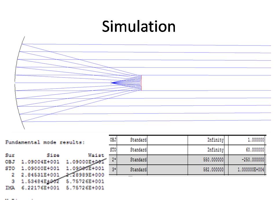
i do simulation in zemax, but i have many choices in the radius
exempt:
reflector is 550
sub reflector is 500
example b:
r1=1100
sub-r=1000
what radius is taken in Overall case?
in general:
D(reflector) is 300mm
D2(sub reflector)50mm
i want to focus the beam after 10 meter, the theory i work with is Gaussian beam
[IMG]

[IMG]

thanks
I do not know where you took the basics of antennas.
There is no "radius"; the primary reflector is parabolic, the secondary is hyperbolic in shape.
At 100 GHz, the accuracy of reflector geometric shape should be better than 0.375 mm, one eighth of wavelength, 3 mm.
Find a good book on microwave antennas for a reliable information.
hi
i know is not radius, its equivalent parabolic\hyperbolic radius, and thanks for the accuracy info.
so how i chose the radius(or f#) for this antenna?
thanks
I am glad you know that the curvature is no "radius".
Aperture antenna diameter determines antenna gain and beam width; this is where you should start.
The secondary reflector in the Cassegrain system will cause a shadow or a reduction in gain, so it is usually chosen to be < 1/5 of the main reflector diameter.
There are various design approaches, generally the attempt is to reduce side-lobe level. Simply take a model and if your software can, generate the radiation pattern. If you like it, fine; if not, repeat the run with a modification.
Many authors claim a successful design by modeling only; the real result often differs. Be ready for this outcome. The easiest way then is to reshape the small secondary reflector or the primary radiator.
hi
"Aperture antenna diameter determines antenna gain and beam width" i think its true in far field, but my antenna is close field. because its small from z Rayleigh.
maybe i can do simulation and see number of radius to be chose.
thanks
You have not mention that your antenna should function in "near-field" zone. If so, then your task is not to design a typical Cassegrain antenna but a special optical system capable to focus on a short distance.
For such task your antenna may preferable be a conical horn, with a correction lens for close focusing. I would not try to design any radiator with a parabolic reflector like a Cassegrain needs. You need a special radiator with a short focal distance. Maybe at 100 GHz, 3-mm wavelength, you could use the light optics like lenses rather than mirrors as in Cassegrain.
hii jiripolivka
first of all thanks for all the info, you help me.
in the first i want to build the antenna with lens but the 300mm lens in this freq(politilen) its to match absorbertion, so i have to do it with mirror.
i need to focus the beam after 10 m. and the min diameter of the main reflector is 300mm.
This is not an easy task if you want to use a mirror.
As I can see you have a modeling software to use, the far-zone in your case is ~60 meters. To focus to a point at 10 meters, you will need to reshape the primary reflector so instead of parallel rays it should hit the second focus at 10 meters.
Once you do it, then you can use a small e.g. 5-8 cm secondary mirror without warping, in the original hyperbolic form.
Another idea may be to use the original Cassegrain system, and add a "metal lens" as a correction element like in Maksutov optic. It will be much easier in a real situation; adjusting the shape of the correcting lens is easier than reshaping the Cassegrain.
And more, with a different correction lens made of metal strips you can refocus to other distances than 10 meters as desired.
hi
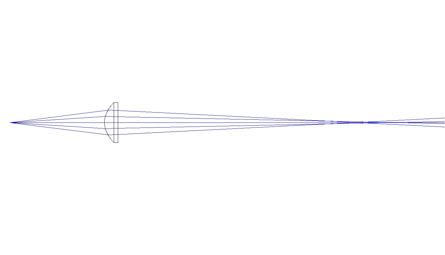
about your offer if i make thin Lens from politilan so maybe its possibly, please see the pic
[IMG]

I know only lenses made of Teflon; I am not sure if polyethylene is low-loss at 100 GHz. Instead of a plastic lens, you can use a "metallic" lens composed of shaped parallel metal strips. Such lens is low-loss and easy to make.
wow :)
ok i tell you the story:
my final Thesis is to build adjustable*focus antenna for 100GHz on 100meter !
i want to build the 10 meter as a start point just to show the principle is work and then go to 100meter
After what you say i dont need this part(10meters) because its More complicated than 100m!
---------- Post added at 22:17 ---------- Previous post was at 22:10 ----------
yes Teflon its what i mean, so with Teflon lens (300mm) and conical horn(witch i have) i can do it? with adjustable focus?
I am not exactly sure what happens, you should check such model. To save the far-field condition at 10 meters, your primary reflector should be not larger than 122 mm.
As I mentioned, instead of fixed-shape reflectors and lenses you can use (or add) the metallic lens to better focus your system at shorter distances than 60 meters.
If I remember correctly, the metallic lens made of metal strips is based on the waveguide principle as the waves travel between parallel plates. It may then be possible by adjusting the distance between the metal strips to tune the phase velocity, and possibly fine-focus the system.
i change to distance between the horn and the lens and the focus point are changed !
so do you think i need to build this from the lens?
There are methods you can use to refocus your optical system.
If you have a single lens and move the point source along the axis, the focus point on the other lens side will move, too.
Or, what I meant was that if you design a metallic lens made of parallel strips, by squeezing the strips together you will change the phase velocity of a beam (or beams) passing through the planar waveguides forming that lens, so its focal length could be varied. You can also try a pair of plastic lenses, and vary the distance between them.
If you have a modeling software like Zemax, you can try what is best.
Or, you can still use the original Cassegrain with an "infinite" focal length, then by adding a (movable) correcting lens like in Maksutov system, you could move the focal length closer as you need.
i have in the lab 100GHz Cassegrain (300mm) from millitech company, so maybe i just adding lens to it(after the antenna).
this antenna is 0.7 degrees.
It may be interesting to measure the beam width over a distance starting from 10 meters from the antenna. MM-wave antennas never focus into a point, from >60 meters (far-field zone) farther , the beam width should be 0.7 degrees. At 10 meters distance, I would expect the beam width is the same but side lobes might be higher than specified.
With a real antenna you can use, I would try, after testing it at >60 meters and ~10 meters, to refocus it carefully (record exact distance between reflectors) while observing the beam width at 10 meters. Refocusing (if the mount allows) could solve your problem.
Otherwise, try a correction lens (a plastic circle like a Frisbee) located at the main dish rim, then move it slowly towards the receiver. Beam width and side lobes would vary but if you are lucky, this way you can find a good result. If not, a "thicker" lens can help.
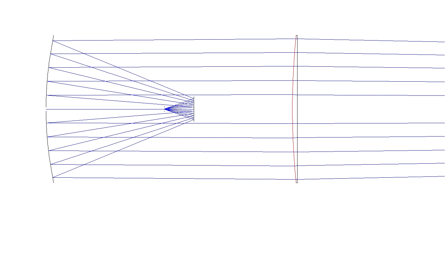
ok i think i do the system on the pic now:
its the Cassegrain from millitech, and the lens i added its focus the beam (the radius of the lens is big-1600)
but what the safe distance (because the side lobes) from the Cassegrain ?[IMG]

As I never did such focusing, I would only guess. But you have the real antenna and lens, so go on and experiment!
Lenses have simple forms, concave or convex; so it is easy to model "rays". With a Cassegrain system, the field close to the aperture is not easy to model. Given that the beam and sidelobes form along the axis up to the far-field zone, I think the safest way would be to install the antenna and a movable(in azimuth ) receiver at >10 meters, and then put the lens between the two, closer to the receiver. Then record the beam form and sidelobe level, and repeat for several distances between the Cassegrain and the lens.
Again, if you are lucky, you find an optimum position.
You can also generate the ray map of your lens, and locate it so it focuses the parallel rays from the Cassegrain to the receive point. Then you can confirm the ray map with pattern measurement.
Modifying the finished expensive Cassegrain would be the last resort to try.
what my professor can do in year ,you do in hour
thanks
i update soon
Dear Erez:
Maybe your professor wanted YOU to try some ideas....
In any case, I can retire soon, you and your professor can have me as a consultant. I have MANY ideas, and I have tried most of them in practice.
- how radius effect on bandwidh and input impedance of a monopole antenna?
- How do you choose input power while doing loadpull?
- How to choose impedance from s2p file to design power divider
- How to choose the right capacitor?
- How to choose the substrate's thickness for a 9.35Ghz application
- How to choose Toroid core for Common Mode Chokes
