Measuring inductance in simulation
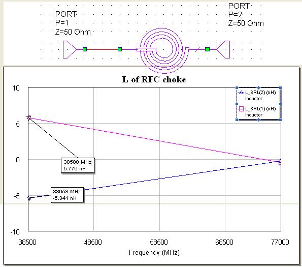
I want to measure the inductance of planar spiral in simulation by MWO. I am currently using L_SRL function in MWO office and getting positive and negative inductances for the two ports. What does it mean?
Which port inductance is the actual one? In the figure attached they are both same in magnitude but they can be varied by changing dimensions.
Thanks in advance
It means that your inductor has parasitics (parallel C, shunt C) and does not behave like an inductor at high frequencies.
Your test setup is wrong..
The coils shouldn't be tested as you have done..
One port must be grounded, the other port is used to get z-parameters..
Then you should compute that..
Of course one port should be grounded. And for better accuracy, you can copy the shape of the inductor from the layout and place it in the AWR EM simulator (and set all the other parameters), and find the L_SRL after the EM simulation.
I do not know the equation used in the L_SRL calculation.
Of course, the inductance can also be extracted from the 2-port setup: L = - imag(1/Y21) / (2*pi*freq)
See The Designer's Guide Community Forum - Inductance extraction: L reduce with frequency?
Thanks everyone, but one question how do we measure the inductance of a stub in MWO.
Vfone: How do I copy schematic into EM. Can you help if I mail you the schematic ?
Thanks in advance
Measuring inductance simulation 相关文章: