Problem: Varactor Based Phase Shifter Design
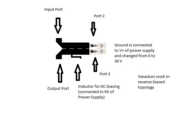
I am using branchline coupler followed by two varactors at port 2 and 3 (port 1 is input and 4 is output).
Although FR4 is not suitable for high frequencies but I am getting S11 and S22 below -14db at 10 GHz
The problem is in Phase of S21,
I am getting no phase change at 10 Ghz in whole biasing range
Instead I am getting phase change at 2 GHz (around 40 degrees phase shift)
varactor diode supports upto 12Ghz frequency.
I cannot figure out any mistake
Need help urgently!
The shape in the picture is not a branch line coupler.
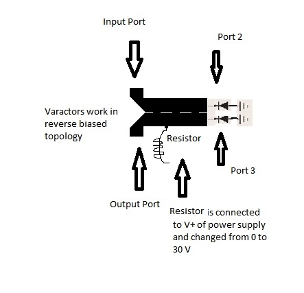
To bias the varactors, instead using an inductor connected to the middle of the coupler, try using two resistors (~100k)
that might be a branchline coupler if all the sections of line were around quarterwavelength long at 10 ghz.
But squinting my eyes and trying to envision a branchline hybrid out of what you drew, it looks like you have one of the varactors on the wrong port.
Its is a 180 degree coupler/ rat race coupler (branch line not circular!)
I am using microstrip inductor for blocking ac and otherwise it will travel to my power supply
Its not a rat race coupler either.
Looks like it is a version of a Schiffman phase shifter.
Schiffman Phase Shifters - Microwave Encyclopedia - Microwaves101.com
The 100k resistor (or two) would block the AC also, and more than this, do not have cut-off frequencies or parasitic resonant frequencies as an inductor.
I am going to use 100k Resistors and will inform about results.
Fingers Crossed!
I checked the design using 100k resistor
Now although S-Parameters are Still fine
S11:-22 dB
S22:-18 dB
S21:-6.4 dB
But now phase shift is restricted to 1 GHz only (Previously 2.2 GHz)
Please Advise!
Need urgent help
I don't have an answer, having only the information you give.
The quadrature phase shifter can provide almost any desired phase shift, but the loads should present purely reactive impedances.
I am not sure you are using the right design for the coupler. Try to make a standard branch line coupler (as in the picture)
Initially I tried Standard Branch line coupler but i was unable to achieve desired S11 at 10 Ghz
Standard Branch Line Coupler has less bandwidth, my design is a modification of standard branch line coupler.
By adding one segment to it, its bandwidth increases
So my modified design performs same (with some compromise on coupling)