AM receiver circuit question ?
AM Receiver
i don't see that it works as an envelope detector , it doesn't have any capacitor in its output , so how does it work ?
thnx
The diode action of the base / emitter junction of the Q3 transistor would act as a diode detector
Dave
the base - emitter junction would work as a half wave rectifier i think , not as envelope detector . still dont understand how it works , can u give a little more explanation ? thnx
A diode is a detector, have a look at any am receiver even something as basic as a crystal set
google crystal set you cant get a more basic am receiver
from Wiki
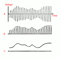
the diode (crystal) detector works.
(A) The amplitude modulated radio signal from the tuned circuit. The rapid oscillations are the radio frequency carrier wave. The audio signal (the sound) is contained in the slow variations (modulation) of the size of the waves. This signal cannot be converted to sound by the earphone, because the audio excursions are the same on both sides of the axis, averaging out to zero, which would result in no net motion of the earphone"s diaphragm.
(B) The crystal conducts current in only one direction, stripping off the oscillations on one side of the signal, leaving a pulsing direct current whose amplitude does not average zero but varies with the audio signal.
(C) The bypass capacitor smoothes the waveform, removing the radio frequency carrier pulses, leaving the audio signal
dave
That's what i am asking about , the bypass capacitor in not included in the diagram , i think it must be connected between the output and the ground to remove the carrier pulses , i see that the 220 n capacitor does not perform this task since it's connected in a form of hypass filter , not bypass . Is that right ?
The 100 nF will act as the filter cap. As large positive half cycle of RF signal pushes Q3 into strong conduction raising bias across 100 nF. Negative going RF signal will drive Q3 into cutoff. The cutoff input impedance of Q3 is high so the positive half cycle RF waveform driven charge on 100 nF does not get discharged much on the negative going RF cycle. Net results is a drop in Q3 Vbe bias so Q3 only conducts on RF positive half cycles.
Circuit assumes your earphones won't respond to RF input frequencies so the earphone is part of the low pass filtering. Collector of output will look more like waveform 'B' on your diagram. If you want less RF on output then put a cap across 10k output resistor.