RFID Module - a nudge in the right direction please for a beginner.
first post....
i've jumped in with both feet and i'm attempting to put together an RFID reader. I'm about to ask some really simple questions so those of you with short fuses look away now
ive purchased this RFID reader: SM130
I chose this one because it claims to be everthing but an antenna.
here is a diagram of the pins:
and here is a picture of the table describing the pins:
so here is my first begginer question
1, The table is clear that the 'Grounds' must be grounded - but to what? what should i be connecting these to?
I have the module stuck into my breadboard at the moment.
another question....
2, how exactly do i create the antenna? is it as simple as coiling some copper and pinning one end into ANT1 and the other end into ANT2?
OK that's probably enought questions for now. i'll see if you guys can give me some pointers on these before i start to ask about data out etc.
many thanks in advance
zac
You have two types of grounds to deal with, the pins designated GND which is simply the ground or return from your power supply. You also have RFGNDs which are RF Grounds that need to be attached to the antenna ground plane, NOT to a power supply ground or return.
Yes and No, it has to be construct to meet certain properties, so many mH for one. You can find several links detailing antenna design in the group:
RFID Technologies
You'll also find many RFID related information in the group, I constantly post new items as I come across them.
Do you have the datasheet and relevant appnotes for this device? If not find the manufactures website or Google the model number of the chip. These are mandatory documents when embarking on a new project.
Let me know if you have any other questions.
Ciao
excellent, thanks so much for replying. i wasnt sure if anyone would or not. This is exactly the kind of feeback I was hoping for.
I shall begin by investigating the link you gave me for the Antenna before posting back some results/findings.
thanks again
zac
I reviewed the available SM130 documents and think, they are missing important informations about the designed antenna matching. ISO14443/Mifare will be using a tuned multiple turn PCB coil, but the details depend on the reader characteristic, that isn't given. Can you tell the chip manufacturer/type of the reader IC? I expect, that you'll be able to make it work with a few turns wire loop, but you would would to match the antenna according to a manufacturer specification. It's also unclear, if a matching circuit is already implemented on the module.
Hi Fvm,
there are some more doc's here
i'm not sure sure but you might be able to see the chip in the pic?
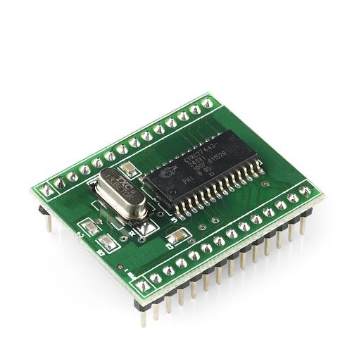
Interestingsly, it's a Cypress programmable PSoC analog chip http://www.cypress.com/?docID=27426 . It's the first time I see it in a kind of retail product. So the detail device properties depend on the programming. It may be meaningful to determine, how the antenna pins are connected (directly to the chip, with additional LC circuit etc.). You'll be able to find out the available pin current strength an estimate a resonable antenna matching from it. Or try to get an exact specification for the intended antenna connecton from module manufacturer.
ok thanks. i just emailed the company to see if they can supply specs for the antenna and they emailled back straight away!
I'm not sure i'm any the wiser though....
What's even more interesting, is that I'm fairly sure I saw a very similar Cypress PSoC based MiFare design entered into a recent Cypress Design Contest. The first PDF, antenna.pdf, the schematic looks strangely familiar and the information block is not filled in.
right, i quickly put this together today. as it helps me to visualise things:
so i think i'm understanding a bit more about the antenna. it needs 5 coils. 3 for grounds and 2 for the antenna. but from looking at the diagrams they are not allowed to touch, this means my original idea of just coiling some copper wire around probably wont work ?
once i get the antenna sorted i then need to move onto how to actually get something outputted when a tag is scanned and i think i do this by using the UART rx & UART tx pins ?
zac
I believe the Cypress PSoC based Mifare Design I previously saw used a multilayer PCB Coil, some of them of course ground planes.
Is this a hobby project, or an actual development project?
The antenna design is quite standard for a proximity 13.56 MHz reader. If I understand right, the module manufacturer sonmicro is selling it as ready made board. The coolcomponents store guys apparently didn't think about offering these necessary accessory.
The problem isn't however, that it won't be allowed to touch the design. The problem is, that you have to tune the antenna circuit anew, and change the capacitors when designing it with different size or number of turns. You can also make very simple antenna matching circuits, e.g a series LC circuit tuned to 13.56 MHz.
P.S.:I would interesting to know, if the design documents are still present somewhere. I browsed the PSoC applications when looking for the part's datasheet, but only found 125 kHz RFID applications.
If you examine CoolComponents PDF link, you'll notice it actually links back to Sparkfun and they have a shield board to mount the SM130 with the PCB Antenna, S20 USD:
RFID Evaluation Shield - 13.56MHz
Unfortunately, it's currently out-of-stock, however they do furnish the following:
Schematic
Eagle Files
So you could produce your own PCB or modify the design for your needs.
---------- Post added at 17:25 ---------- Previous post was at 17:12 ----------
Here's another source for the same shield:
RFID Evaluation Shield - 13.56MHz
And it's in stock. Zac123, purchasing one of these for S20 USD would most likely be the relatively painless solution to your problem.
100% hobby!
---------- Post added at 18:44 ---------- Previous post was at 18:33 ----------
many thanks. let me work through the links you've given me and see what i come up with. i did think about buying the antenna but i guess i just wanted to do some of the manual work myself
i'll get back with my progres.
zac
You certainly can design your own antenna, especially with the schematic and Eagle files provided by Sparkfun. However, having a known working antenna platform could come in handy when troubleshooting your own design.
You may already be aware of this fact, but unfortunately many are not;
Any RFID tags or cards you purchase to test your device are required to be 13.56MHz MiFare specific.
Good Luck with your project and antenna design.