constructing an antenna at 13.56MHz
I need to construct an antenna at 13.5MHz for RFID application.
Reader and Tag are inductively coupled so reader and tag antenna coils can be seen as a transformer.
Can you please guide me how to construct the same with lumped circuit elements?
I have to simulate and check how signal and energy is dictributed at the secondary coil (Tag) and the rectification part in cadence.
-shaikss
The combination of reader and tag coil can be sufficiently modelled by two inductors with a coupling factor.
I guess, your next question is about the numbers.
- Well, it depends on the geometry
Hi FvM,
I have tried to build a circuit and simulate using Spectra in Cadence but couldn't succeed.
This is the way how I have gone:
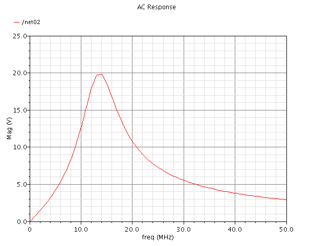
1. Initially I built parallel resonator circuit and checked the simulation. The simulation shows the center frequency as 13.56MHz.
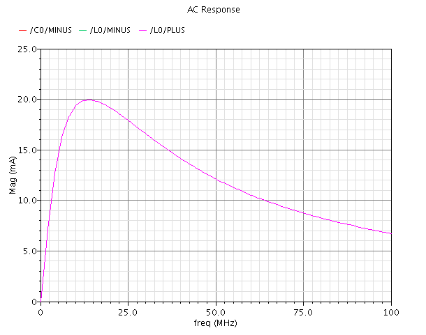
2. Then I built a series resonator circuit and did the simulation. Again ran the simulation and its center freq is 13.56MHz. I have attached its waveforms. I am OK with the response.
3. Later, reader coil was constructed using series resonator circuit and tag was constructed using parallel resonator circuit. Here is my doubt. How to make the circuits couple each other? What are the changes do I need to do in order to see the coupling effect?
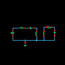
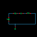
I treated series resonator circuit as reader coil and parallel resonator circuit (without any voltage source)as tag coil. attached is the figure.
First fig: simulation of parallel resonator circuit
Second : simulation of series resonator circuit
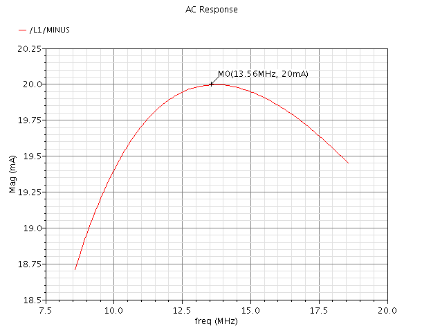
Third: Simulation of Reader coil and antenna coil
Fourth : Reader and antenna coil
Fifth: Series resonator circuit
If you see the fourth figure, when I connected the tag coil to ground and checked the response, tag coil has 0mA of current which means it is always grounded and reader coil has a resonance frequency of 13.56MHz. Then I attached a 1ohm resistor in between reader and tag coil, then the resonant frequency shifted to 17MHz.
Can you please let me know what are the changes to be done and what needs to be corrected? In practical means, inductive coupling happens between the reader and tag. I am not getting how to realize the same in cadence environment. But how to realize the same using lumped components in cadence? I am newbie to this and so help me.
http://images.elektroda.net/81_1314353923.png
http://images.elektroda.net/56_1314353923.png
http://images.elektroda.net/85_1314353923.png
http://images.elektroda.net/67_1314353923.png
http://images.elektroda.net/72_1314353923.png
I can't imagine, that inductor coupling isn't provided in Cadence. But I'm not using the tool, so I'm not aware how to set it. I suggest to consult the manual.
P.S.: Some additional points to consider.
- card coil design. RFID standards, e.g. ISO_IEC 14443 have magnetical field strength specifications. The number of turns for the card coil results directly from this field strength range and the card respectively coil size, and required tag circuit voltage.
- reader coil design. There's a relation between operation distance and reasonable coil size, see the below NXP application note. Coil Q is suggested by the modulation bandwitdh respectively envelope rise/fall times required by the standard. Q often has to be reduced by additional resistors related the original coil parameters. Number of turns is usually low (1 to 4) to limit the resonant circuit voltage to acceptable levels.
- coupling factor of both coils results from the above discussed basic geometry. Low percent values can be expected at "operation volume" boundaries for proximity cards.
- 2.5D or 3D AC magnetic simulation tools are helpful to determine the parameters of a reader/card geometry. I did many simulations with fasthenry, a free tool from fastfieldsolvers.com.
http://www.nxp.com/documents/applica...te/AN78010.pdf