How to make MOSFET to operate in Subthreshold region
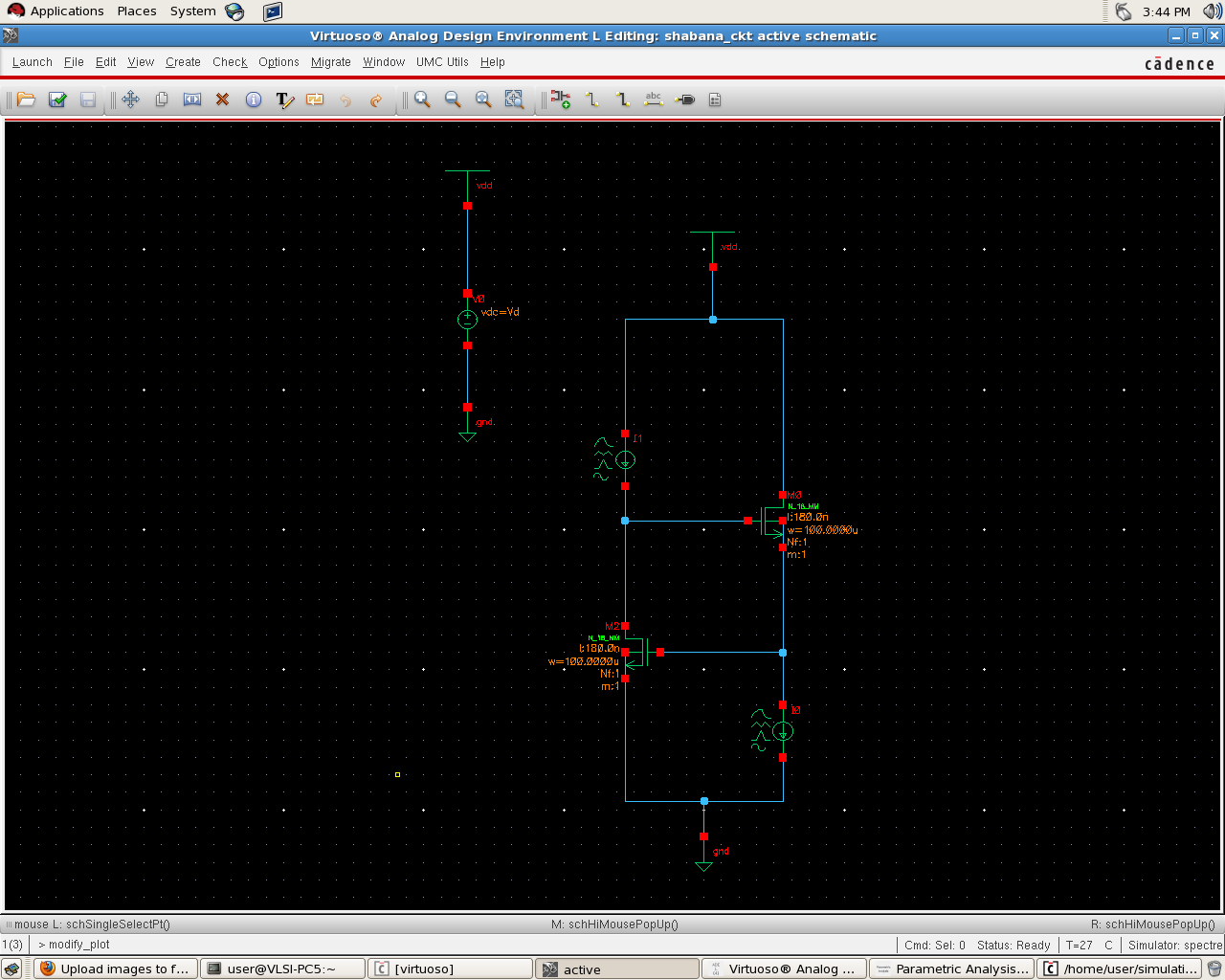
Attached is the schematic of the circuit.
I want to operate M2 in subthreshold mode and M0 in saturation region.
Can you please let me how to do this cadence?
How to check the operated region (Sat/cutoff/linear/sunthreshold) of mosfet in cadence?
Where can one view the region value (0/1/2/3/4)?
I did Results -> Annotate -> DC operating point. But I couldn't succeed in finding the region.
Please help me out.
Thanks
It's quite easy to make this,just consider the definition of those two terms.
Sub-Threshold (for nmos) : Vgs<Vth
Saturation (for nmos) : Vds>Vdsat
1.)Perform dc analysis
2.)From the top menu of ADE L window find the choise Print DC Operating Point
3.)Hit on the transistor of interest
4.)Read the report that comes up and finally
5.)Check the validity of the above inequalities to verify the region of operation
This was useful. I got to see the operated region. Thanks Jimito.
What are the various ways/methods employed to increase/decrease Vgs or Vds in my scenario? I am newbie to analog design.
Give me a hint in my scenario to make M2 in subthreshold and M0 in Saturation region. I am confused
Thanks
There's basically only one method. Setting I0 and I1.
Hi FvM,
When I1 < 700nA, M2 goes into breakdown mode.
When I1 is In between 1uA and 700nA (inclusive of the limits), M2 is in subthreshold mode.
When I0 > 1.5mA, M0 is in Saturation region except for 0-400mv.
0<Vd<=400mv, M0 is in triode region. From 400mV onwards, M0 goes into sat region.
I tried varying I0 till 2.5mA, I observed the same behaviour.
How can I make M0 in Sat region from 0<= Vd <= 1.8V? I varied I0 for the wider range. But I observed that until 300mV, M0 is in triode region.
The circuit is designed to behave as an active inductor.
Can you please let me know how to proceed further?
I want to operate the circuit such that M0 is in Sat and M1 is in Sub threshold region.
Till now, I did dc analysis.
Whatever behavior I have observed is the expected one? Any correction is required in the procedure?
Please help me out.
Can someone help me out pls?
PS: With the above values of current sources, I can see only the real part of impedence. I don't see any imaginary part when I plot a graph impedence Vs Voltage. What should I do inorder to see the imaginary part of the impedence? I am indesperate need of help and its very urgent for me.