Rectifier simulation in cadence
时间:04-07
整理:3721RD
点击:
Hello All,
I have simulated the FW rectifier in cadence.
Have attached the schematic, reference schematic and plots of input and output.
I have given Vsin from analoglib as input voltage with amplitude 5V, frequency of 1KHz.
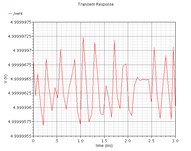
When I simulate the design and check the voltages at net of positive of Vsin, I couldn't get the actual sinusoidal waveform of freq 1KHz.
Can you please explain why is it happening so?
I have replaced the Vsin with Vpul. The problem is same.
I am not getting where the problem lies. Hope you can help me.
My question is : Why the input sinusoidal waveform is not looking like a pure sinusoidal waveform?
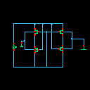
First Fig: Schematic of the design
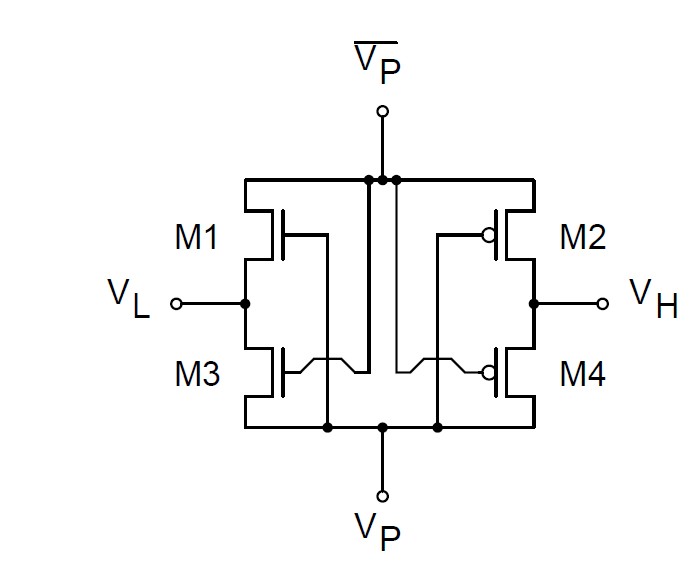
Second: Reference design
Third: Input voltage when Vpul is given
Fourth: input is sinusoidal vol
I simulated the design and plotted the nets connected to plus and minus of input voltage Vsin. Actually, the expected plot is pure sinusoidal waveform but I see different one.
Where did I commit mistake and how to solve it?
http://images.elektroda.net/41_1314951513.png
http://images.elektroda.net/100_1314951513.png
http://images.elektroda.net/0_1314951513.png
http://images.elektroda.net/78_1314951513.png
I have simulated the FW rectifier in cadence.
Have attached the schematic, reference schematic and plots of input and output.
I have given Vsin from analoglib as input voltage with amplitude 5V, frequency of 1KHz.
When I simulate the design and check the voltages at net of positive of Vsin, I couldn't get the actual sinusoidal waveform of freq 1KHz.
Can you please explain why is it happening so?
I have replaced the Vsin with Vpul. The problem is same.
I am not getting where the problem lies. Hope you can help me.
My question is : Why the input sinusoidal waveform is not looking like a pure sinusoidal waveform?
First Fig: Schematic of the design
Second: Reference design
Third: Input voltage when Vpul is given
Fourth: input is sinusoidal vol
I simulated the design and plotted the nets connected to plus and minus of input voltage Vsin. Actually, the expected plot is pure sinusoidal waveform but I see different one.
Where did I commit mistake and how to solve it?
http://images.elektroda.net/41_1314951513.png
http://images.elektroda.net/100_1314951513.png
http://images.elektroda.net/0_1314951513.png
http://images.elektroda.net/78_1314951513.png
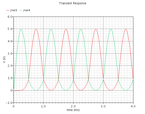
You need to plot voltage across vsin. In your case, it should be net3-net4.