Choosing the right photo diode.
I do not understand how do I select the photo diode to be used. Most of the photo diodes I saw have a peak sensitivity at around 900nm. All these have wide detection ranges. I understand that I will have to package my device such that sunlight does not fall on it. But how do I make sure that the photo diode detects only the laser beam? There are circuits given for detection in the datasheets but all values are constant or depend on the op-amp that is being used. How does the photo diode detect a particular wavelength.
I did study optical communication but I honestly don't remember much. Please help me out.
Thank you.
Regards,
Pooja
Hi, no photo diode, rather use photo transistor. I show You simplest laser alarm. Laser beam falling on phototransistor and when beam is break output is active. You can use open or close detection state.
Phototranssitor is LTR4206 3mm, IRE5 5mm,.... laser torch is chinese very chip torch 630-680nm with max output 1-5mW of course You can use stronger lasers.
Sunlight does not affect on phototransistor in this circuit. Phototransistor activate only when strong beam of light point on it, such as laser beam, even on distance over 200m.
If You whant to activate when breaking beam - Place phototransistor on NC points.
If You whant to activate when beam si detected - Place phototransistor on NO points.
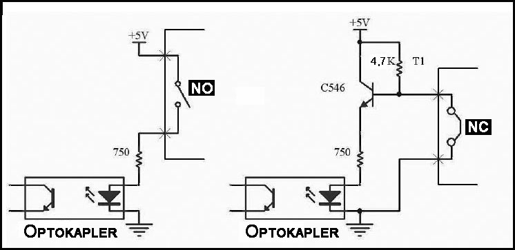
Of course You can always use 12V or different voltages just adjust resistors and no problems.
Use a optical filter in front of detecting diode reduces problem with sunlight. A good filter for 650nm can reduce the sun with more then 95%.
It is very common to frequency-modulate source with few MHz so receiver can then also filter in frequency domain for unrelated light-noise.
If laser beam rotates with 600 rpm can you synchronize your receiver (PLL) when to expect a signal, which can improve total s/n.
Use optic lenses at receiver end so photo-diode only can see a few degrees of total field, collect as much as possible of light radiating from source and focus it on detector area, then can additional 95% or more of unrelated light be filtered and your optics will give a gain in a similar way as a directional antenna.
There are no light-detectors that have a natural max sensitivity at 650nm, as fare as I know.
Where can I get more information about phototransistors? I have never worked with them. Can you please explain that circuit?

Phototransistor put instead of switch.
Phototransistor datasheets from Internet. Knowledge best comes from the exercise. Circuit is simplest as can be, You can make it in 5min.
Depends from design, scenario and circuit goal which to use, photodiode or phototransistor. Phototransistor is smaller, in my expirience and better for photodetecting, can give more sensitivity then photodiode.
Open any device with photodetection part, You will always find phototransistor not photodiode!
Earlier, you asked for photodiode wavelength and filtering :
Material Electromagnetic spectrum
wavelength range (nm)
Silicon 190?1100
Germanium 400?1700
Indium gallium arsenide 800?2600
Lead(II) sulfide <1000?3500
Because of their greater bandgap, silicon-based photodiodes generate less noise than germanium-based photodiodes.
Also photodiode sufer from dark current. The current through the photodiode in the absence of light, when it is operated in photoconductive mode. The dark current includes photocurrent generated by background radiation and the saturation current of the semiconductor junction. Dark current must be accounted for by calibration if a photodiode is used to make an accurate optical power measurement, and it is also a source of noise when a photodiode is used in an optical communication system.
The minimum wavelength which can be detected by silicon is around 400 nm (using special blue-enhancement technology also shorter wavelength is possible). At about 880 nm a maximum of sensitivity is reached and then sensitivity decreases and is almost zero at 1100 nm. Hence silicon devices can be used for detection of the visible range (400 nm to 800 nm) and for the infrared range of electromagnetic radiation (800 nm to 1100nm).
For applications where infrared LEDs are used as a light source there is no need for the detector to be sensitive in the visible range. In these cases photodetectors with so called ?daylight filters? are used. This is simply a black epoxy mold instead of clear epoxy mold. It is blocking the radiation in the range of 400 nm to 800 nm whereas the radiation above 800 nm will pass the epoxy with almost no loss.
The photo current of phototransistors is quite high compared to the current of photodiodes. The phototransistor is composed by a photodiode and an amplifying transistor. In most cases the amplification factor of phototransistors is between 1000 and 1500 which results in photocurrent of some 100μA or even few mA. On the other hand photodiodes are much faster than phototransistors. The raise time of photodiodes is some ns typically, whereas the raise time of phototransistors is some microseconds.
The photo current of the photodiodes is proportional to the size of the chip. To get a high photo current in an application the chip size has to be chosen as big as possible. Quite generally the photodiode chips are much larger than the size of the phototransistor- dice. As a consequence many photodiode chips do not fit in the same housings as phototransistors and hence much less housings are available for photo diodes.
Photo-transistors and opto-couplers are usable solutions to use for detecting if something blocks a dominant light-source, but free field over some distance, outdoor and maybe sunny daylight will it not work if your laser source is a much weaker light-source then total amount of light that your detector can "see".
A typical circuit to be able to do initial measurements: Linear Technology Circuits - Photodiode Amplifier.
The photo-diode can be replaced with a photo-transistor in this circuit but you cant use it as a amplifying transistor as it is reverse bias.
Do you actually know, that the laser beam has 3 mm diameter at the detector? This would refer to a rather limited distance, because the beam is divergent
In my view, if you are using the detector in open field, you can't exactly exclude, that the detctor will be exposed by direct sunlight, e.g. if the sun is low and in the same direction as the laser source. IN so far, it may be a requirement, that the detector still works with direct sunlight. That's not impossible, but need some special means.
Narrow optical bandpass (interference) filters are in fact the most effective means to reduce enviromental light. But they may be not easily available. Daylight as well as incandescent lamps will still have some spectral power within the filters passband. So in addition, the dtector circuit must be able to handle some DC current and the photo detector must kept from saturation. You have been initially asking for photo diodes, which seems to me more approriate than photo transistors, that become easily saturated at higher intensities.
You should be able to know the laser ouput power from a specification. With the actual beam diameter, you can calculate the power density at the detector and estimate the photo diode signal.
P.S.: There's usually no problem of a direct laser beam being too weak, even at a considerable distance, and a beam widened to e.g. 10 or 20 mm.
This circuit what I give works on 250m with chinese chip laser 1-5mW on open at daylight. I think that you mix optocoupler with photodiode. Optocoupler cant be used for this purposes he have built in led diode with phototransistor (sealed in epoxy). In my circuit I use optocoupler to isolate main circuit from sensors.
If the detector is intended to work at near distance as well, we should consider a considerable share of the total laser power hitting the detector. Silicon photodiodes have about 0.5 A/W sensitivity at 670 nm, so with respective detector area, a photocurrent up to mA should be calculated. I imagine a good and cheap standard diode like BPW34, with 2.65 x 2,65 mm area. Unfiltered sunlight gives about 0.5 mA photocurrent with BPW34.
A setup to measure the speed of light? (if yes: cool, keep us updated)
Like Kafeman said, you should modulate laser with some frequency. That way sensor will see some slowly changing base level (caused by sunlight etc), with superimposed some fast changing level when laser passes over the sensor. Then you can use a high-pass filter to separate laser signal from background level.
You should choose modulation frequency high enough that there's at least a number of periods in the time it takes the laser beam to pass over the sensor (I suggest some back-of-the-envelop calculations to get a feel for the numbers). You could increase this 'laser pass window' by using a bigger sensor (or multiple ones?), such that it takes more time for the laser to cross the sensor's surface.
Then select a photo diode / photo transistor with fast enough response, poor sensitivity to common daylight/sunlight wavelengths, but good sensitivity to the laser's wavelength. And if possible use an optical filter to filter as much of the non-laser light as possible (to increase signal/noise ratio). And/or construct a kind of tube with insides painted pitch black, with opening pointing at laser.
Why? You get short pulses from the rotating laser in one upto ten us order of magnitude.
Well exact numbers would depend on laser beam width, RPM (both given), sensor size, sensitivity and distance laser <-> sensor (not given / unknown @ this point).
But you're right! If laser beam sweeps the sensor's surface short/fast enough, that should be enough to filter signal from background, no need for modulating the laser beam itself.