[Moved] Low Noise Amplifier design

I think you'll get more responses in the RF, Microwave, Antennas and Optics section.
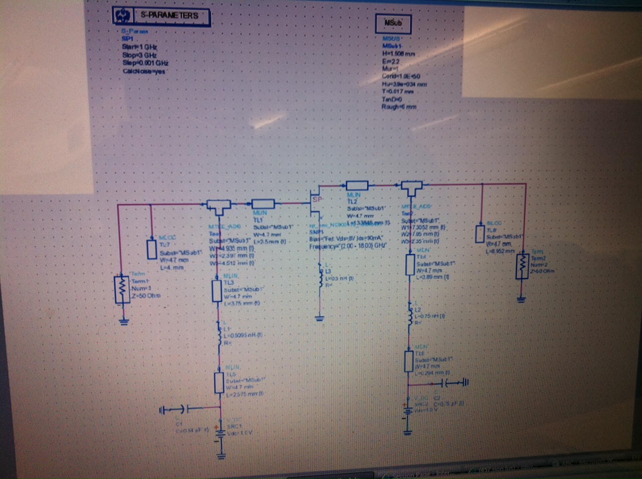
I am not very sure about the transistor you are using, but it seems to be a power transistor. it is very probable that you can not get a good Noise figure from it. Have you tried to draw the noise and gain circles of the transistor?
Hi osilvab, many thanks for the reply; i've tried to draw the noise circle but it gives a single arrow pointed to the negative side of the smith chart, and the gain circles give me a big circle on the negative side of the smith chart, do you really think it is the transistor that causes all this?
Many thanks in advance.
Well. its not common at all to have an arrow instead of a circle. for LNA design you should always start for the input to ensure a good NF, for that the most practical is to draw Noise circles at different levels, and Ga gain circles so you can have a feeling about how much gain are you trading for some noise. I suggest you to review the theory a bit, the Gonzalez book its good for that. Then you will realize if it is the transistor or not. which is the minimum Noise figure in the datasheet of this transistor?
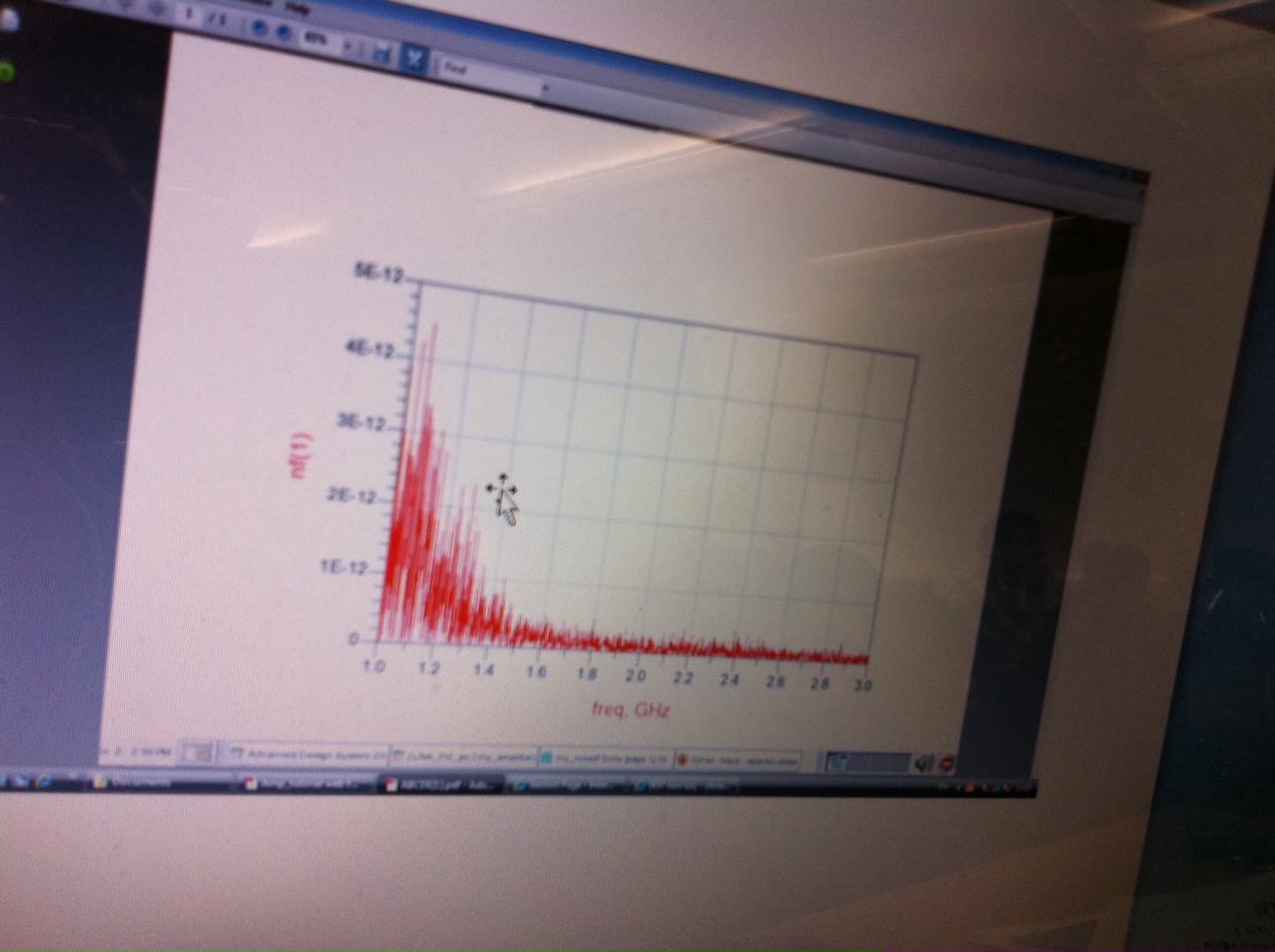
edit: by the way I am not sure but I think the NF of your interest is nf(2).