microtrip hairpin filter dimension and spacing
i hav designed microstrip hairpin Bandpass filter for ISM band with dielectric rogers 6.08...got width and spacing from various papers available...but it wont be very accurate ...u hav to try reducing width to get lossless response........
by what you mean various paper, do you have any example of quasi static graph...i can't hardly find it anywhere...
u try to get any IEEE papers related to dat topic for the design of hairpin structure....im not sure of quasi static graph...i designed using ADS software...
Just build your hairpin filter in ADS's schematic and then use optimization to find the parameters, it will take less than half an hour
thanks for your information but sadly, Hamid, i didn't have the ADS software....they only provide me with CST...and the software price really cost me, and i ca't afford it. I've been struggle with this quite a long time... could you please hamid, help me...
If you have the required even and odd mode impedances, you can use a transmission line calculator to calculate the coupled dimensions.
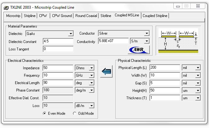
Here is a free calculator: AWR | TX-LINE | Optional Products - TX-Line
This one can only do "reverse" for coupled lines, i.e. from physical dimensions to even/odd mode impedance, so you have to iterate the dimensions manually.
AWR is a good way for optimising the filter. And AWR is much cheaper than ADS.
In this situation, volker_muehlhaus has given a good suggestion. Get the dimension from this method and then simulate in in CST.