100 ohms differential trace dimensions?
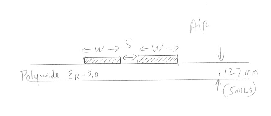
My best guess so far is W=100 mils, and S= 4 mils. Traces are on flex board (5 mil thick polyimide er=3.0).
Thanks, Rich
There is no unique answer. Z0=SQRT(L/C). Somewhat oversimplified: You can change the C by decreasing the gap width, or change the L by changing the line width.
I have modelled the line in Sonnet which I think you are using. The model file is attached.
Below is the plot of the line impedance vs. line width for two different slot widths (2.5mils and 5mils). As you can see, you have 100 ohm differential impedance for w=40mils@s=2.5mils and also for w=90mils@s=5mils.
Thanks volker. That is very helpful. It is for an RFID antenna at 915 MHz printed on a flex pcb.
What is that file format ".zon" that you attached? Can that be imported into sonnet lite plus?
This is the "packed project" with results. Import it into the Sonnet editor with File > Import > Packed Project.
Thanks. I wish I had a few days to sit back and just play with Sonnet and learn all these tricks. I am learning along the way (i.e. the "hard" way).
ohms dimensions differential 相关文章:
- Calculate dBm from dBuV without Ohms
- Why we have to use always 50 Ohms at the input and output port
- What should i use S21 when matched to 50Ohms or pure S21 when choosing FET?
- 25 ohms connector or termination for PCB
- 50 ohms Microstrip line CST simulation
- Table of dimensions for a phased planar array antenna ?