Drawing and calculating the equivalent circuit of an antenna
I want to draw the equivalent circuit of an antennas but i don't know how should I draw it?I simulated my design in CST.
How should I calculate the lumped element of each segment of the radiator?
In the antenna designing we only have a conductor patch to radiate , feeding pin, short pin, substrate and the ground plane, so how can we create capacitance or inductance effect in that structure?
and more important form where we conclude that which length of the radiator works as a capacitance or inductance ?
would you help me please? :?
There was a similar topic a few days ago:
https://www.edaboard.com/thread235518.html#post1009445
thanks I wrote my comment there.would you please visit it.
Talking about equivalent circuits, we probably should add equivalent in what regard. In a first order, an antenna's equivalent circuit would be expected to approximate it's impedance with a certain accuracy. It won't allow relating lumped circuit elements to individual. antenna elements, because it hasn't to do with the 3D electromagnetical behaviour of the antenna strcuture. Expecting a relation respectively information about radiation patterns and similar properties of the real 3D device misses the nature of the electromagnetic phenomena, I fear.
Dear FvM
Do you know what's the equivalent circuit of this antenna?
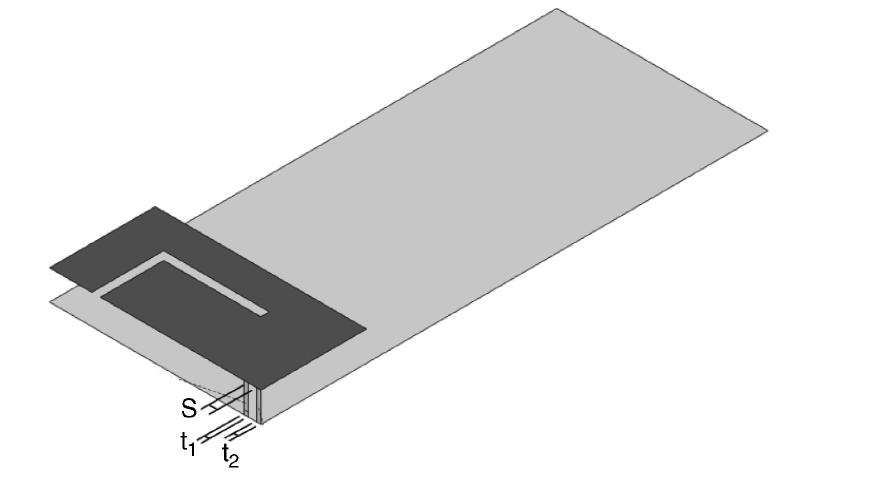
and dose this equivalent circuit tell us what's the E field distribution of the antenna or not?
I am afraid you misunderstand something. Equivalent circuit models are not useful in antenna design. The antenna is a distributed (not lumped) radiating structure. An equivalent circuit model is lumped (not distributed) model that does not include radiation. Even if you try to approximate the input impedance of an antenna with an equivalent circuit model, this does not tell anything about the radiation properties.
Dear volker_muehlhaus
thanks for your reply
in fact I found something in antenna designing that by controlling the near field characterize I can tune the far field distribution.
one of the near field feature is Input impedance .when it is high the antenna radiate well.
for example I calculate the input impedance by smith chart and in the resonate frequency it was equal Z(in)=78-j16.
so I need the equivalent circuit to show me the input impedance of the antenna in a frequency band of 300-600 MHz.
I know in 402MHz the antenna has the large value of the input impedance and it radiate well.
do you believe that here the equivalent circuit is useless too?
Instead of large input impedance, you'll try to a achieve a large radiation resistance which is the real part of the impedance.
While the input impedance is a primary property of the antenna, an equivalent circuit is just a simplified representation of this impedance. As already discussed, also in the linked previous thread, you'll have some difficulties to design an accurate equivalent circuit valid for a larger frequency range, and it's nothing but an arbitrary circuit that hasn't more information than the s11 smith chart or a table.
A smith chart is a much more visual tool for antenna calculation and tuning or e.g. to design impedance matching circuits.
calculating Drawing equivalent 相关文章:
- Calculating total radiated power (TRP)
- calculating corner frequencies for oscillators
- Help on calculating active s-parameters in CST
- Calculating Resistance/Capacitance values from measured/simulated S-parameters
- Need help with Calculating S11 Using HFSS
- Calculating area of sphere within particular angular range