Help with design of inset feed patch antenna
I need to match the impedance of a patch antenna that will operate @2 GHz.
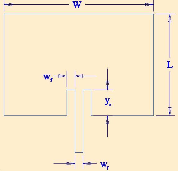
I calculated all the paramenters but i cannot find anywhere how to calculate the walue of Wf
Can someone help me out?
So, is there actually no equation in order to design the dimension of the microstrip line?
Did you consult balanis's book?
i think this book has all the necessary design equation.
cheers
Yes, i read the entire chapter of patch antennas but i couldn′t find that equation...
http://www.google.com/url?sa=t&sourc...LFRa5i-bilqi4g
The width of the microstrip line (Wf in your picture) is given by the line impedance (usually 50 Ohm).
The slot width (equal to Wf in your picture) should not be critical.
---------- Post added at 15:29 ---------- Previous post was at 15:26 ----------
Isn't that a different case, with probe feed instead of line feed from the side?
Wait...I don′t think I follow..what do u mean by given?the output of my generator is at 50 Ohm, does it matter the length of the line or its width?
Yap, the paper looks to be a different case, but I will try to read it anyway, maybe some new ideas...
Thanks for the reply
yes, of course.
Ok...so let me put this straight.. I have a patch antenna that I want to feed with a microstrip line.
The output of my generator is at 50 Ohm.
can someone tell me EXACTLY how to design the connection between the generator and the antenna?
I already calculated the value of all the parameter of the antenna, I just need the microstrip line!
Thanks
Design the line for 50 ohm line impedance, then the length does not matter.
Here is a calculator that helps to determine the required line width, for a given substrate material and substrate thickness:
Microstrip Line Calculator | em: talk
Can you help me out with the "electrical length" parameter?
Many thanks for your help...
This is the phase between input and output. It is not relevant for your matching, if the line and generator are both 50 ohm.
ok, but I need anyway to put a value...
Put in anything, for example 1 degree or 90 degree phase delay. It has no effect on the calculated width.
You will not find an EXACT formula that gives you all dimensions. All such formulas to get a first guess for design are approximations and have a certain (limited) validity range.
I assume you have a simulator to refine your first guess before building it. Increasing the length of the inset reduces the impedance (at the feed point), reducing the overall length of the patch increases the resonant frequency. These two things you need to adjust your first guess towards a satisfying input return loss.
As your feed point for the S parameter measurement or simulation will not be at the inset edge, you need to correct for the phase rotation of S11 due to the electrical length of the microstrip line.
I hope you are not going to build it on 1.6mm FR4 glass/epoxy laminate. I assume this antenna is for you gold dispersion challenge.
i've been trying to solve the impedance calculations for the transmission line to have a 50ohm matching all these days.thank you for the response here, now my design is complete...
adios