simulating the "Stripline parallel-coupled lines filter" on Advanced Design System
There should be an option for importing the layout from AutoCAD into ADS.
Draw the layout in AutoCAD and import into ADS.
-sv
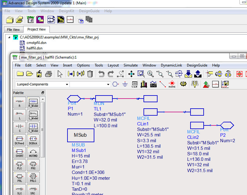
Have a look at the ADS example mw_filter_prj
Use "Passive Circuit DG - Microstrip Circuits" if you have license..
It's much easier than drawing..
thank you. but imported file cannot consider the coupling effect. in addition, how can I use the imported file in schematic design (maybe those file are useful in momentum but how about optimization and ...)
---------- Post added at 12:23 ---------- Previous post was at 12:18 ----------
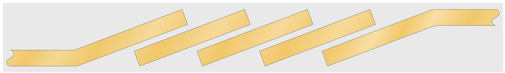
thank you. but I think this structure is different with my request. Look at the angle of the strips.
---------- Post added at 12:26 ---------- Previous post was at 12:23 ----------
thank you. but I cannot find any structure in "Passive Circuit DG - Microstrip Circuits" regarding my request.
The only difference is the bend at the filter input/output. You can use element MBEND.
parallel coupled simulating 相关文章:
- Parallel coupled line Band pass filter
- Biasing with parallel (series LC) at input
- Active antenna parallel to main antenna in V/U Handheld?
- MOS parallel to antenna - antenna clamp, antenna modulator
- Dielectric resonator between two parallel microstrip lines. What current direction?
- Parallel plate wave guide problem