Very small notch (and feed width) for a inset-fed microstrip antenna, is it correct?
时间:04-06
整理:3721RD
点击:
Hello!
I'm designing a microstrip antenna which is going to be fabricated by drilling it out of a FR4 laminate with the specs:
h = 0.08cm
For the frequency 866 MHz (using it for RFID), the parameters i"ve calculated are:
W = 10.640 cm
L = 8.346 cm
inset length, y0 = 2.875
So far i think it all looks good, but when i"m calculating the inset width and feed line width i'm getting some odd numbers.
The calculator over at emtalk.com gives me 0.156 cm microstrip line width while the formulas in Balanis book (3rd edition page 825, chapter 14.2.1) gives me 0.123 cm width.
These seem awfully small, is that because of the substrate being so thin or have i made an error calculating it?
I have this posted in Electromagnetic Design and Simulation as well, but i think that is the wrong forum!
---------- Post added at 15:57 ---------- Previous post was at 14:27 ----------
That"s my design in CAD, green being the filled antenna and feed, red line being the ground plane.
I'm designing a microstrip antenna which is going to be fabricated by drilling it out of a FR4 laminate with the specs:
h = 0.08cm
For the frequency 866 MHz (using it for RFID), the parameters i"ve calculated are:
W = 10.640 cm
L = 8.346 cm
inset length, y0 = 2.875
So far i think it all looks good, but when i"m calculating the inset width and feed line width i'm getting some odd numbers.
The calculator over at emtalk.com gives me 0.156 cm microstrip line width while the formulas in Balanis book (3rd edition page 825, chapter 14.2.1) gives me 0.123 cm width.
These seem awfully small, is that because of the substrate being so thin or have i made an error calculating it?
I have this posted in Electromagnetic Design and Simulation as well, but i think that is the wrong forum!
---------- Post added at 15:57 ---------- Previous post was at 14:27 ----------
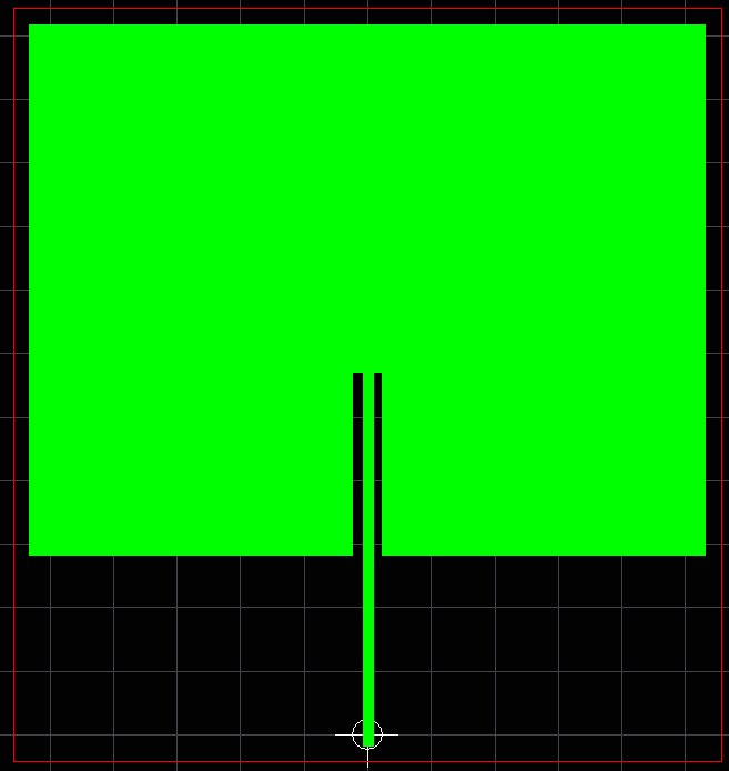
That"s my design in CAD, green being the filled antenna and feed, red line being the ground plane.
These 1.56mm are consistent with results from another transmission line calculator (AWR txline).
This is a reasonable, expected value for 50ohm line impedance at 0.8mm substrate height.
I have not checked the inset length, but the ratio/shape from the picture looks reasonable.
The tolerance on FR4 dielectric constant is poor 10%? and lower than expected @ 1GHz also much lossier than desired for high Q notch. Consider GETEK FR4 10x better. Looks approx like 1/4 wave stub with 1/2 wave feed. Good luck.