AC current and Electromagnetic wave propergation
How current, near and far fields are related, depends on your geometry, and of course wavelength. Maybe you can give some additional information.
I'm following a module called "Fundamentals of Microwave engineering" in the university. I have learnt of Transmission line theory.
In this circuit, I wonder what does this lines represent, normal conductors or kind of microwave link between two antennas..
Sorry I am still in the basics.... :)
Hello,
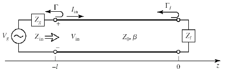
This makes sense. If this is your first introduction, the diagram shows a lossless transmission line (coaxial cable, two wire line, microstrip, strip line, etc) with source and load. The cable parameters are Z0 and beta (2*pi/lambda).
It is used to explain the concept of interfering travelling waves (that cause change in impedance and standing waves) This concept can be applied to any other medium that supports waves (sound, RF waves, waves in liquid, etc).
In non-guided wave propagation (such as radiowaves), the math is more elaborate as the reflection depends on the angle of incidence. The interference between the reflected waves and incident waves depend on their mutual orientation (complicating the math).
Transmission lines fall into the wired transmission category. Transmissions lines can "leak" energy into space, although this isn't considered in the basic transmission line description. By using a coaxial or other closed transmission line geometries, radiation can be suppressed.
Then I guess I can apply this theory to waveguides also. If its ok, what does voltage and current means in such a transmission? And also in here there are two conductors, one we can consider as the reference. But in waveguides I think we don't have two connections.
Another question that had arisen was how power transmitted along a coaxial cable? Is it like a normal conductor or like a waveguide?
Yes, you can apply the wave and impedance concept to wave guides. In a slotted wave guide, you can even measure the standing waves with a microwave diode detector.
When looking to a rectangular wave guide in its fundamental propagation mode, you have the highest E-field at the center line (vertical E-field component), hence a voltage between the bottom and ceiling of the guide. There is also a ongitudinal surface current density in the bottom and ceiling part, hence a net ac electric current. So in fact you have two connections, but for DC you have a short circuit via the vertical walls. If you have a wave guide mixer, the diode is between the bottom and ceiling.
The impedance concept is used when treating various wave guide components.
Coaxial cables you can see as two normal conductors. The H-field encircles the inner conductor and the E -field is between the inner and outer conductor (radial field).