audio modulation in a simple TV transmitter
I am trying to build Tetsuo Kogawa's simple TV transmitter with audio following the instruction here: http://anarchy.translocal.jp/microtv...edTVTX_p0.html (Before this I have tried, successfully, to build the silent version of the transmitter with no audio at http://anarchy.translocal.jp/microtv/howtotvtx.html and the circuit works upon first power on).
This time, I started with building the audio section of the circuit (http://anarchy.translocal.jp/microtv...edTVTX_p2.html), which is essentially an LC oscillator @ 5.5MHz (for PAL B/G audio subcarrier used in Singapore). I do not have the 2SC transistor so I replaced with a 2N3904 instead. I also removed the 1K variable resistor that attenuates the audio input and connects the audio from my VCR directly to the 10uF capacitor. I build everything on a stripboard. I am using a 47uH resistor-like inductor with a 35pF trimmer capacitor. Using the formula L*C*(2*pi*f)^2 = 1, I estimated the frequency to be around 3MHz - 11MHz.
However, upon completion of the audio section (without the main section), I used my oscilloscope to check the output (after the 10pF capacitor). The circuit does not oscillate at 5.5Mhz no matter how I adjust the trimmer capacitor. The oscilloscope frequency counter is random. In fact, the output waveform resembles the input audio, although with much lower magnitude.
Any advice on what might be the problem? I seriously do not think there are any connections issues - this is my 3rd attempt, all with same results.
Thanks in advance :)
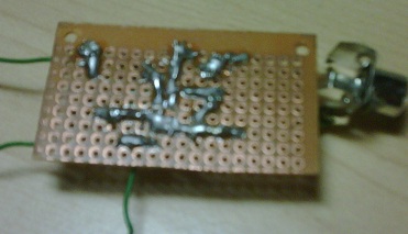
I attached pictures of my build (front and back) on a veroboard.


That was a rather primitive circuit. A single 100uF decoupling capacitor for V+ may be stable enough to let the circuit oscillate, maybe not, but as minimum add a 100nF ceramic capacitor.
This is a very low quality FM modulator. why not use a IC built for this propose? Either a general FM oscillator or a specific for PAL, if it still exist.
Can not see any coil in your LC-design? Make it low loss, high Q, for best oscillation. Using standard inductance can be possible but they have often high loss at higher frequencies. Check data sheet.
confusing post the real schematics or draw one yourself ...more u may have wrong substitute or wrong pinout connection between the transistor.
do u have a nice clean sine wave ?
what about your scope input cap ?
check in dc scope mode post wave form use ltspice
Thanks all for the replies. I got the audio section working by:
+ Removing the 1000pF from the emitter
+ Places a 100nF capacitor in parallel with the 100uF decoupling capacitor.
The inductor I am using is, by the way, a green resistor-like inductor. it can be seen on the top right of the photo, just above the trimmer. Will post back if I have any more questions. Thanks.
modulation audio simple 相关文章:
