Designing Microstrip Ring Resonator A 1GHz
时间:04-06
整理:3721RD
点击:
Dear All,
I am trying to design a twin-port Microstrip Ring resonator @ 1GHz using HFSS, for that I am using Rogger 5880 [e= 2.2, tand=0.0009] with the height of = 0.787mm and copper for feed line, ring & ground-plane with thickness 0.0175mm.
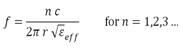
I calculated the width of line using ADS LINE CALC which give width= 2.3981mm (for both ring and feedline) and Eeff = 1.875, and using
For the feedline length I take a random value of 35mm and put the coupling gap = 0.638mm
After that I have make complete design on HFSS, then draw two rectangular sheets and assign them ?waveport? (sheet height is 10 times > substrate thickness i.e = 0.787x10=7.87mm and sheet width is 8 times > width of feedline i.e 2.3981x8 = 19.1848) and then also assign my ground plane as ?perfect E?.
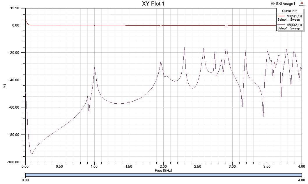
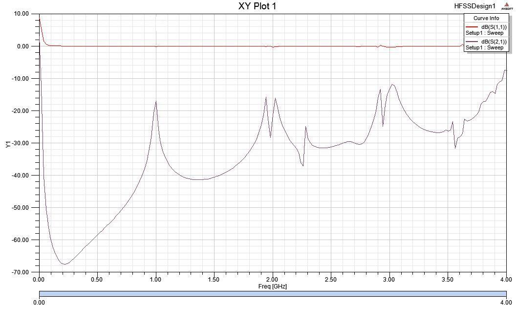
Finally I make a boundary around my microstrip; the box having a height of 150mm which overlap the entire structure along with ground plane. When I simulate this design on HFSS it give some spurious results even it isn?t showing periodic resonances,
I tried several times while making some changes in design, like increase substrate edges at ring corners, increase/decrease the height boundary box, but still I haven?t get any good response. Here I have attached dimensions of my design alongwith the results.
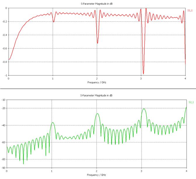
Meanwhile I make a same design on CST but it gives different result, it shows resonances on 1, 2, 3GHZ?.with some distortion, but now I haven?t get an idea how to get proper result on HFSS.
HFSS Results
CST Results
I have assessment on next week and have to present my work so much worried about my results, plz guide me
Thanks
I am trying to design a twin-port Microstrip Ring resonator @ 1GHz using HFSS, for that I am using Rogger 5880 [e= 2.2, tand=0.0009] with the height of = 0.787mm and copper for feed line, ring & ground-plane with thickness 0.0175mm.
I calculated the width of line using ADS LINE CALC which give width= 2.3981mm (for both ring and feedline) and Eeff = 1.875, and using
For the feedline length I take a random value of 35mm and put the coupling gap = 0.638mm
After that I have make complete design on HFSS, then draw two rectangular sheets and assign them ?waveport? (sheet height is 10 times > substrate thickness i.e = 0.787x10=7.87mm and sheet width is 8 times > width of feedline i.e 2.3981x8 = 19.1848) and then also assign my ground plane as ?perfect E?.
Finally I make a boundary around my microstrip; the box having a height of 150mm which overlap the entire structure along with ground plane. When I simulate this design on HFSS it give some spurious results even it isn?t showing periodic resonances,
I tried several times while making some changes in design, like increase substrate edges at ring corners, increase/decrease the height boundary box, but still I haven?t get any good response. Here I have attached dimensions of my design alongwith the results.
Meanwhile I make a same design on CST but it gives different result, it shows resonances on 1, 2, 3GHZ?.with some distortion, but now I haven?t get an idea how to get proper result on HFSS.
HFSS Results
CST Results
I have assessment on next week and have to present my work so much worried about my results, plz guide me
Thanks
Microstrip Designing Ring 相关文章: