Measuring PLL loop bandwidth
PLL Loop Filter nth degree low pass filter and it can be measured with VNA or Signal Generator with Powermeter.
There are lots of ways. One way I like is to insert a phase shifter between the reference ocillator and the PLL chip.
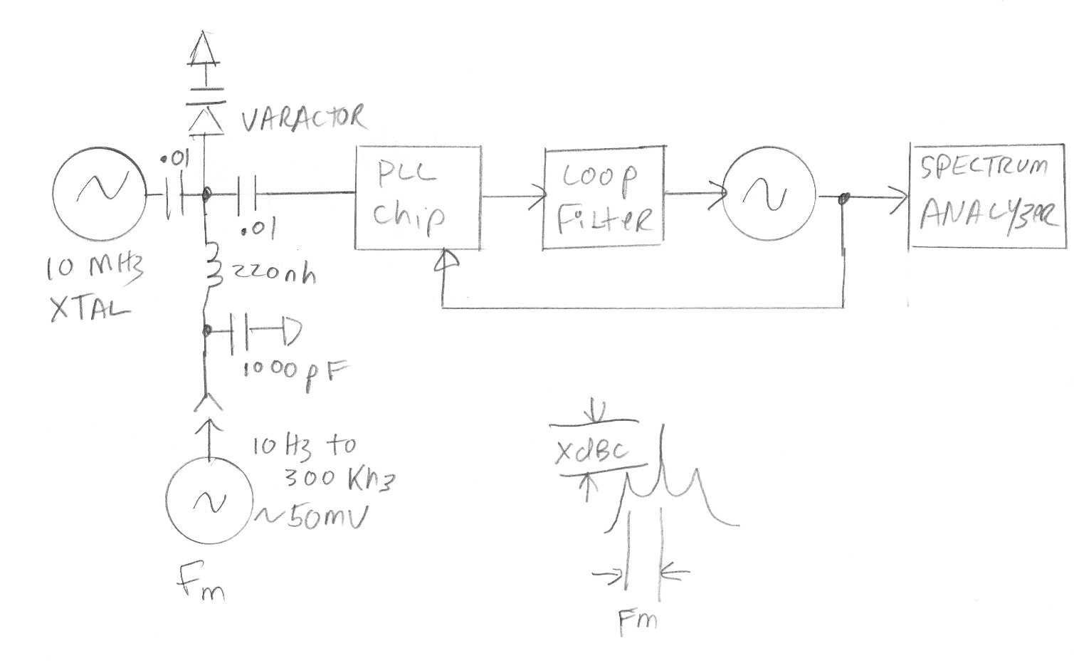
You apply a few degrees of phase modulation with the varactor diode to the reference. Since the PLL is "phase locked", it will make the oscillator track that phase modulation when the frequency of the phase modulation is within the loop bandwidth. When the microwave VCO stops tracking that modulation, you are beyond the loop bandwidth.
So you set up an external lab generator set to maybe 1 KHz and attach it to the varactor. You look on your spectrum analyzer and see two sidebands, +/- 1 KHz from the carrier. You adjust the external lab generator so that the two sidebands are easily seen, maybe 30 dB down. then you leave the level fixed, but vary the frequency higher. the sideband level in dBc down will stay fixed until you get near the loop bandwidth.
At that point, if you have a well damped loop, the spur level will be 3 dB lower than the other values, and at that exact Fm frequency, you know your loop bandwidth. If, on the other hand, you have a poorly damped loop, or maybe even an unstable loop, the sidebands might actually peak up 6 or more dB at the loop bandwidth frequency before heading down again. That tells you to play around with your loop filter parameters, especially your zero frequency, until the peaking mostly goes away.
Rich
You can also try to measure it directly:
Measuring the Loop Bandwidth of a PLL
http://www.radio-labs.com/DesignFile/dn003.pdf
Thank you all for the solutions. I have another basic question. If I place a freq. doubler after VCO will the VCO gain/tuning sensitivity [MHz/V] also get doubled for loop bandwidth calculations?
IF the pll chip sees the microwave frequency after the doubler, the tuning constant will act like is is doubled.
IF the pll chip see the direct VCO frquency, and elsewhere in the circuit you double the frequency, then the tuning constant is unchanged.
other parameters of interest are Lock-in time vs BW , or #of cycles required to lock-in vs BW which is also affected by loop gain and phase noise filter and phase margin pf loop.
Normally I prefer adaptive gain loop bandwidth to change response time so wide band to capture then narrow band after locked on. such as with a 10: 1 ratio or higher, making sure not to inject phase error during the crossover. It is also natural for effective loop gain to decrease somewhat with signal/noise ratio near threshold , measured in comparative terms such as lock in time, overshoot etc.
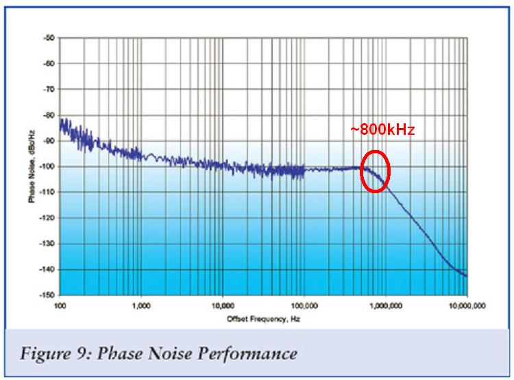
If you have a Spectrum Analyzer with a Phase Noise profile, just measure the Fo and look where the
Knee is. That will be your effective Loop BW.