Pin diode switched line phase shifter
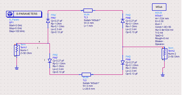
I have been working on switched line phase shifter.There is a circuit shared which is i want to implement.
I have no experience implementing pcb of microstrip circuit.
Will this circuit work in real, if i set up
Do you have any video,tutorial vs to help me implementing circuits with microstrip?
Your PIN diode circuit needs DC blocking capacitors and bias resistors/inductors.
Take a look to this informative paper about PIN diode circuits:
http://www.qsl.net/n9zia/pdf/pin_diode_handbook.pdf
thanks, but i already examined this handbook.If you look switched line phase shifter there is no added bias circuit at page 8.
...page 7 (and many others) shows the bias of the PIN diodes...at page 8 is just a symbolic schematic, to show the main configuration of the circuit.
Whatever configuration is used (switch, attenuator, modulator, phase shifter), a PIN diode needs a bias circuit.
I am not familiar to rf circuits.
There is a circuit in foundation of microwave eng. which is easy to implement because of microstrips so you dont have to
interest inductors or capacitors.

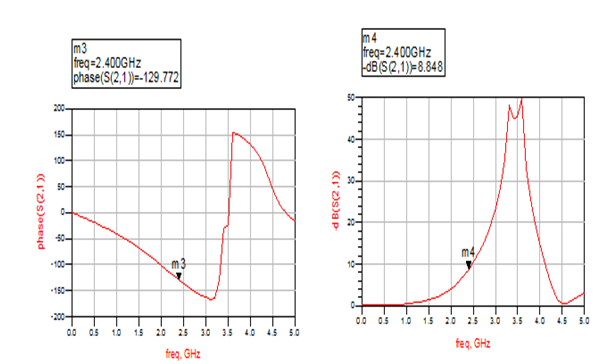
I designed it for 45 degree phase shift but ads simulates properly if there is bias or not.
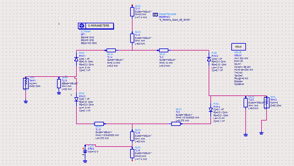
The point i dont get it is what should i connect to upper bias point ? -10 V? Nothing?
And i am going to use this pin diode.
http://pdf1.alldatasheet.com/datashe...HP/1N5767.html
Yes, in your situation have to feed the circuit with a negative voltage (positive to the ground), but this needs to be done using a series resistor for current limiting.
1N5767 is a medium power PIN diode and the bias current (function of the RF resistance) could be between 1mA and 100mA.
In your situation because the diode is used as a switch, have to provide high current for low RF resistance. So, the series bias resistor and the DC supply gives you the current through the PIN diode.