Gali-74+ amplifier faliure issue
Thank you for sharing your knowledge for my previous quieries.
please consider the scenario where a 13dBm output from a GALI-74+ amplifier is provided to the ADP-2-20+ power divider (both from Minicircuits)
I have utilized the above method to divide a 60MHz frequency into two paths ,
it was found during testing that the amplifier is not providing the required gain ( only 7dB gain is present instead of 24dB gain).
I have arrived at a conclusion that the lower input return loss of the Power divider (ADP-2-20+) has resulted in the reflection of the signal to the amplifier and caused it to fail.(The maximum input of the amplifier is 10dBm as per datasheet)
please guide me through this issue.
I would be surprised if you have destroyed it in the way that you describe as these devices are really very robust if treated normally. I would think that static damage is more likely or that the dc bias conditions are wrong on the output. Check that you don't have any solder splashes shorting the input and output blocking capacitors and check also that the device is drawing the right bias current. After you've done that I would replace the device and make sure that you have soldered down the ground paddle on the back correctly as any inductance here from an inadequate joint will lower gain and may affect stability too.
I hope this helps...
OldRFguy
ThanQ for your reply,
after replacement of the failed amplifier it was found that the amplifier is providing more gain for 120MHz component and lesser gain for 60MHz component,
is this problem related to the any soldering issues ?
a) Is your amplifier oscillating?
b) Is your input/output DC blocked? Which capacitor?
- - - Updated - - -
a) Is your amplifier oscillating?
b) Is your input/output DC blocked? Which capacitor?
The amp is rated down to "DC" but the data sheet does not post what the actual gain would be at 60 MHz. Maybe it degrades as part of the internal bias network?
Also, make sure the DC blocking caps are big ones!
Please post your schematic, including the bias T and blocking caps.
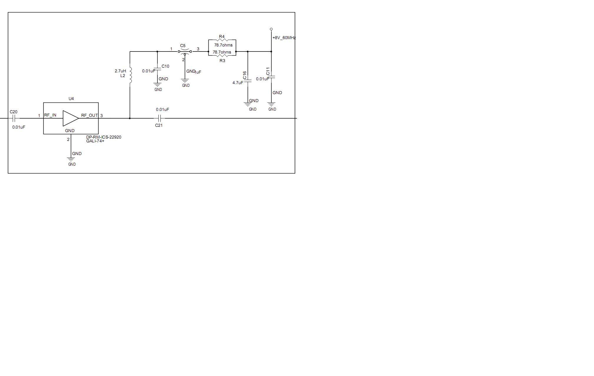
i have attached the schematic above for the amplifier alone including its biasing components)
C20 and C21 are ATC520L103KT16T from ATC ceramics
L2 is 0805LS-272XJLB from coilcraft
It's possible and also coupling capacitors may be cracked during soldering because they are very sensitive.If output coupling capacitor is cracked, the amplifier can potentially oscillate and it can destroy
the active device..