microstrip line phase shift for broadband design?
The longer the microstrip line is,the much phase shift is. I need 270degrees shift ,10 degrees variation could be accepted. thanks!
Heya rf1008,
As you've found, lengths of transmission line work fine as phase shifters for single frequencies but are useless for broadband operation. For wider bandwidths (on the cheap - i.e. without using turnkey solutions such as http://www.minicircuits.com/products...Shifters.shtml), I've had a great deal of success with combinations of flux-coupled transformers and/or microstrip branchline couplers (e.g. http://www.microwaves101.com/encyclo...e_couplers.cfm).
If you have a simulation/design tool like Agilent's ADS to hand, optimising the branchline coupler (for which there's even a macro in the component library) for a given frequency range is relatively straightforward. While I'd suspect your biggest difficulty would be optimisation on FR-4 (given the wide range of possible dielectric permittivites shown by this substrate), in practice if you design for a 'typical' value of e_r you'd most likely meet your +/- 10 degree spec at 1 GHz.
Good luck!
Hi thylacine1975, thanks for your information.
I simulated my circuit by ADS, wilkinson power devider and two ustrip lines, the two output ports have same amplitude and about 180degrees phase difference. Attached are my results.
[ATTACH=CONFIG]76737[/ATTA
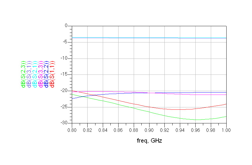
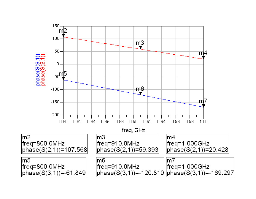
Please all you help to check, thanks.
you can do something called a "schiffman" phase shifter, that has a quarterwave coupled line section in one arm, to make the phase shift relatively flat vs frequency. You should be able to get 800 to 1000 MHz with a few degrees of unflatness.
http://www.microwaves101.com/encyclopedia/Schiffman.cfm
You set the length to be quarterwave at 900 MHz, and vary the Zoe and Zoo until the phase shift is flat over frequency.
If you need it to be variable, you could add shome shunt varactor diodes or tunable capacitors for a small variation.