Re: Can I use active loop filter here ?
But I am concerned about single supply of the amplifier. Are you familiar with these conditions?
The Vdd = 1.2V suggests that it's a RF IC design and the loop amplifier a part of it. In so far I expect that the single supply situation has been considered. But without substantial information about the observed problems this aren't but guesses.
If no nonlinear element is allowed, how can I check the stability of active LF with nonlinear MOSFETS? I have a good model for ac and transient analysis. But the model is prepared for passive LF. So, as of now, my main concern is the stability analysis of PLL loop with active LF. And what is the problem with single supply?
If you want to perform a stability check in the frequency domain (BODE diagram) you need a linear PLL model.
This implies that the PLL is in lock condition and the state variable is the phase.
Therefore my question: Did you develop already a linearized PLL model in the frequency domain? For example, in such a model the VCO appears simply as an integrator Kvco/s.
Ya such kind of model is with me, using which I designed 1 passive Loop Filter PLL. But the same model is not sufficient, as I found, because of non-linearity present in Active LF. So, how to overcome the problem of non-linearity present in Amplifier
- - - Updated - - -
In other words I previously had a model of PLL with passive Loop Filter. But now I want a model for Active LF. The main problem I am facing is the non linearity of Amplifier
In this case you have a bad design (bad amplifier).
How do know that the amplifier is non-linear? Are you sure?
For simulation purposes (ac simulation) you just need the transfer function of the filter (LAPLACE block) - independent on hardware realization (active or passive).
I don't understand your problem. You can perform a PLL simulation with your real nonlinear amplifier, varying the amplifier output voltage by an offset voltage source or the setpoint parameter of the PLL model and check the loop stability over the full operation range.
Hi FvM, are you talking about ac simulation? Fvm and LvW, I am really thankful for your continuous support.
As per my observation, when I put CMOS amplifier in Loop Filter and perform PLL stability analysis, I get an unstable system, but the same active LF giving me stable output in transient model.
Yes.
Are you also talking about AC analysis? What do you see in detail?
C3 C4 reduce ripple but make loop unstable for capture. remove them
let C2= 10xC1 and adjust R in series with C2 for adequate capture range
I need to know worst case error frequency of VCXO in Hz & PPM
Then I need to know VCXO gain Hz/volt and control range (Hz) hopefully that is centered in Vcont range.
Last I need to know loop filter Bandwidth -3dB
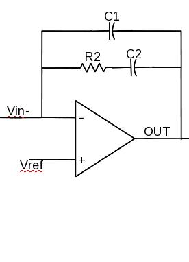
My 1st question is can I use this structure in PLL stability analysis(AC analysis)? My all other blocks are modeled with ideal elements (from analogLib)
yes Does PD have a switched output to feed inverting input?
if yes then no change for integrator
then apply rules I have used in the past on real designs above
Yes, the PFD polarity is reversed in case of Active LF
I am mentioning my observation
When I put passive LF in AC model, the Vctrl(dc)=1.2e-22 and the system is stable.
So, if I use my active LF here, the Vctrl should remain at this dc value only, but this value will put my Amp in linear.
That is the reason I cant the use CMOS amp in AC analysis
Are you joking?
I presume, Vctrl means the VCO input voltage? A reasonable operation point for the stability test would be well in the middle of the supply voltage range.
Ya I agree, but all blocks are modeled with linear ideal elements. So, for me, it should not matter what is the value of Vctrl, as long as my dc Feedback voltage( o/p of Divider) is equal to Ref voltage.
If working with real OP models instead of behavorial components, you must adjust the PLL model to enforce a vctrl value according to the real VCO.
A simple behavioral VCO+PD model is just an integrator. The reference level of integrator input determines vctrl in steady state, it should be Vdd/2 rather than 0.
A linear analysis of a PLL is not useful, since none of the parts are linear. What happens to your result when the signal exceeds the linear range of each part. eg. VCO control, PD input range .
My recommendation: Read again post #16 and 24.
A linear analysis is the only way to collect some information about stability margins. However, one has to be aware of the restrictions of such an analysis.
Yes Linear Bode Plots are 1st cut at the design for reducing jitter and overshoot, but do not readily determine capture range, lock-in time and other non-linear characteristics.
It is certainly true that a linear analysis cannot provide non-linear system characteristics.