Class-E Power Generator for Vacuum plasma power supply & Impedance Matching Question
I?ve no any RF PA background, but I?ve already studied ZVS Class-E PA and Impedance Matching for about a month, I still have plenty of questions.
The equivalent Impedance after igniting, is about 500 Ohm and equivalent capacitance in parallel, but still Varied with different gas in Vacuum chamber or states, I use Simulation Attachment 82116test specific load condition, and it could Match with Optimum Designed Output impedance Seen from transformer primary leakage inductance side. But If I need to use this at different load , means different Vacuum Plasma Chamber, the Impedance Won?t Match , So I have to use Variable Capacitor in Impedance Network for any load condition , As I change the output Resistance , Is it possible to change the resistance part seen from RF power generator output by change Variable Capacitor in Impedance network only ? (which transformer?s turn ratio and inductance must be fixed) and what kind Impedance matching network should I choose is more proper?
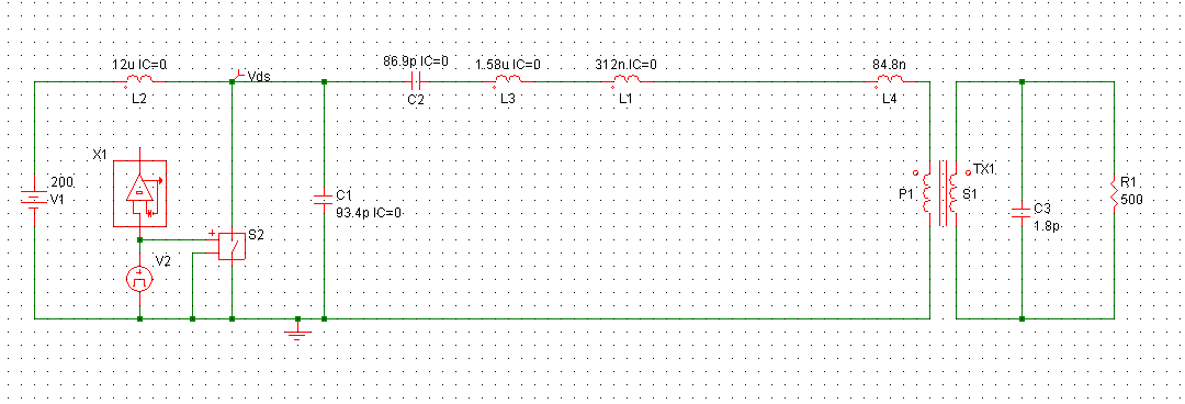
Class-E Power generator with step-up transformer and plasma Load
Edaboard says "Invalid Attachment specified."
By nature, an impedance matching network with a single variable capacitor can't be adjusted for X and R (respectively phase and magnitude) matching at the same time. A common impedance matching tool is Pi low-pass filter with two varcaps, for a larger matching range, the L should be stepwise variable too. You also would want to have a directional coupler to measure forward and reflected power.
Thanks for your opinion, I'll study for pi low pass Impedance matching network later.
I have another question about reflected power. Because as I studied so far, I understand When The ZVS Class-E Power Generator Designed Optimum Output Impedance Don't Match the Impedance matching Network.
The MosFET won't Operate under ZVS, which reduce the efficiency, and the calculated Drain to source voltage and current stress also increased, some drawback could happen.
So could I Simply think that The reflected power is that cause the Power generator work un-optimum and could be considered as "reactive power" ? (If designed optimum Resistance contain no reactance )
How does it effect my system ? Vin is purely A voltage source form PFC Output voltage
and if the frequency is 13.56Mhz , is the Reflected power problem effects severely?