Design: Mixer : single balanced : Ratrace : question
时间:04-06
整理:3721RD
点击:
I want to design a mixer [ input : Lo@1.9Ghz , IF@100Mhz ] [ output : RF@2Ghz ]
I used ratrace and designed it in ADS so it will work good enough @1.95Ghz ( the average of LO and RF)
now the next step is connecting diode and ...
I have some basic idea. I read Maas book. For example I will use Microstrip Radial Stub to get rid of LO and RF at IF port.
I first wanted to see how good my diodes (hp_HSMS2702 can not change it -university project ) are matched.
the first question pop up...
1. at which frequency ? I dont know my diodes should be matched? since the device is 3 port (check datasheet) it brings many question.
I guess IF port (the middle one) should be matched to Z0=50ohm @ 100Mhz and the others should be matched to Ring(rat race) impedance which is sqrt(2)*50ohm @1.95Ghz(average of Lo and RF).
but Im still not sure.
anyway I wanted to check S parameter of my diode and ...
I used many ways
I read from this forum that we should use LSSB so I used LSSB simulator @2Ghz ( correct me if im wrong)
like this
and the result was like this
which is really bad
I tried also HB
and used the formula = (V[8]+50*I.i[8])/(V[8]+50*I.i[8]) ===> index 8 corresponds to 2Ghz
result:
but the res look similar but the value are not the same because LSSB is using Z0 and I don't know how to compare these results?
which one is correct?
3.
now if I want to match the IF port the middle port of diodes to 50 ohm is it correct to do this and use S-simulation:
which simulator should I use? S-parameter or LSSP?
I used ratrace and designed it in ADS so it will work good enough @1.95Ghz ( the average of LO and RF)
now the next step is connecting diode and ...
I have some basic idea. I read Maas book. For example I will use Microstrip Radial Stub to get rid of LO and RF at IF port.
I first wanted to see how good my diodes (hp_HSMS2702 can not change it -university project ) are matched.
the first question pop up...
1. at which frequency ? I dont know my diodes should be matched? since the device is 3 port (check datasheet) it brings many question.
I guess IF port (the middle one) should be matched to Z0=50ohm @ 100Mhz and the others should be matched to Ring(rat race) impedance which is sqrt(2)*50ohm @1.95Ghz(average of Lo and RF).
but Im still not sure.
anyway I wanted to check S parameter of my diode and ...
I used many ways
I read from this forum that we should use LSSB so I used LSSB simulator @2Ghz ( correct me if im wrong)
like this
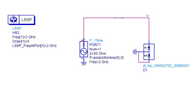
and the result was like this
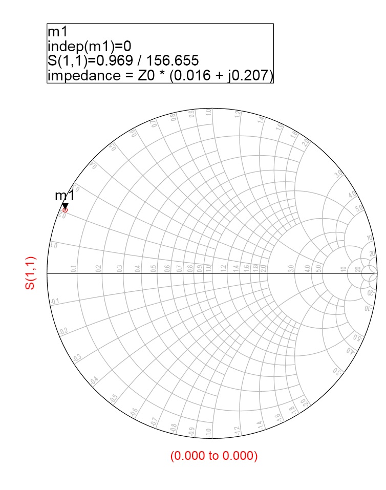
which is really bad
I tried also HB
and used the formula = (V[8]+50*I.i[8])/(V[8]+50*I.i[8]) ===> index 8 corresponds to 2Ghz
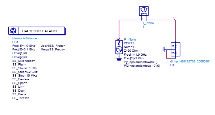
result:
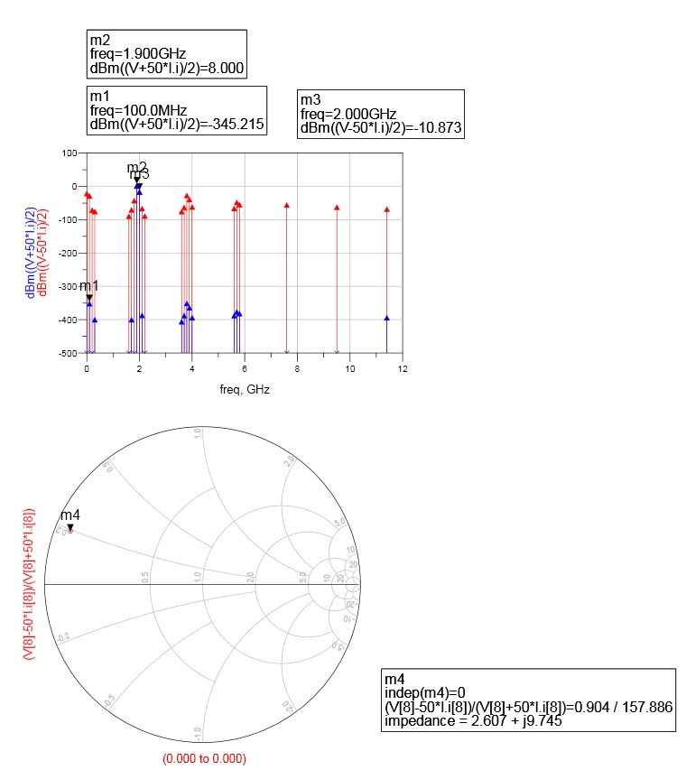
but the res look similar but the value are not the same because LSSB is using Z0 and I don't know how to compare these results?
which one is correct?
3.
now if I want to match the IF port the middle port of diodes to 50 ohm is it correct to do this and use S-simulation:
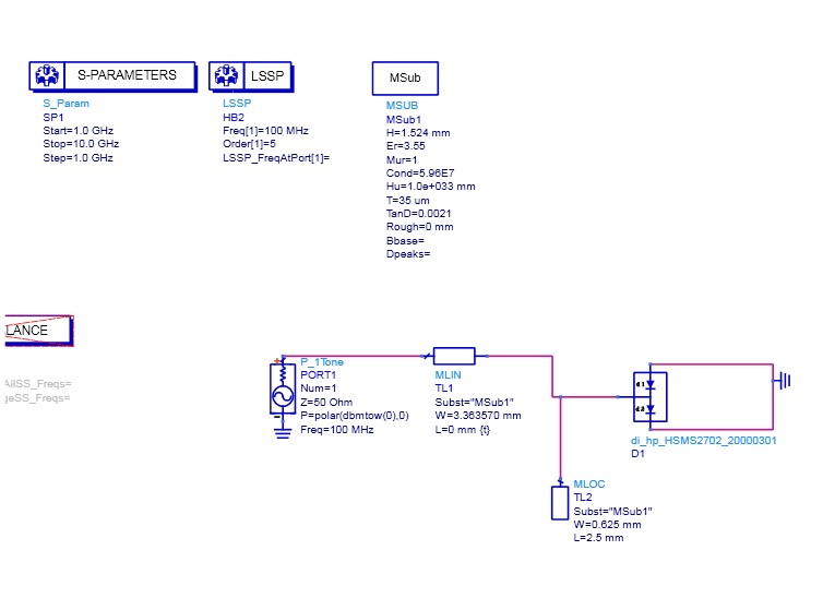
which simulator should I use? S-parameter or LSSP?
- How to unballance this single balanced mixer?
- How does single signal reception work in this transceiver?
- Can a transformer be used to convert single ended signal to differential signal?
- Single TCXO For Multiple ICs
- Monopole antenna is single ended or two terminal?
- Need help on single stub matching problem.
