any sample code for rfid reader using EM4095 for 125khz? how to write the code?
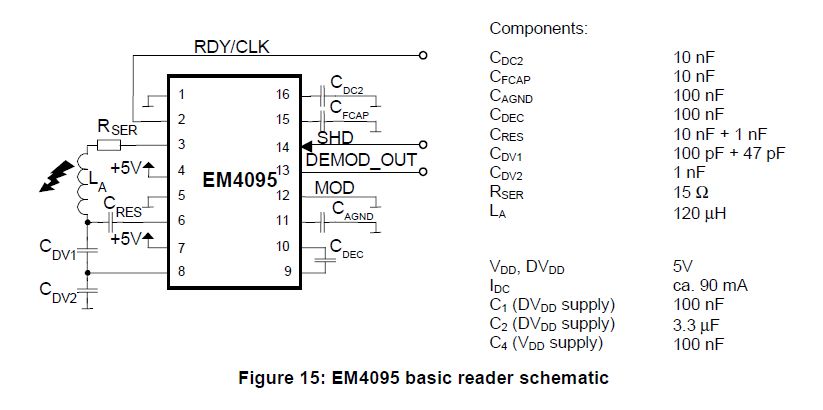
i am designing a RFID reader ckt using EM4095 for 125khz. i got the ckt from "EM4095 Application Note" ,but i dont know what protocol is used to communicate with tag(400x) , i interfaced the RFID reader to PIC16F877A.
can any body give the link for sample code for RFID reader using EM4095 ?...
ckt is attached ...
The following is an example in MikroC, however you should be able to adapt it to another C Compiler. The PIC16F877A may not offer system clock frequency high enough to sufficiently service the interrupt routine.
/*
 * Project name
     RFiD (Displaying CRC check of RFid card via Usart)
 * Copyright
     (c) mikroElektronika, 2010.
 * Revision History
     20091220:
       - initial release;
     20101021:
       - added active comments, sbit approach, code reorganized...
 * Description
     The code demonstrates using two external interrupts to read data sent
     by EM4095 chip (clock - RDY/CLK; data - OUT).
     Upon correct identification of the card, results are displayed via USART
     along with the card specific number.
 * Test configuration:
     MCU:             PIC18F4520
                      http://ww1.microchip.com/downloads/en/DeviceDoc/39631E.pdf
     Dev.Board:       EasyPIC6
                      http://www.mikroe.com/eng/products/view/297/easypic6-development-system/
     Oscillator:      HS-PLL, 32.0000 MHz
     Ext. Modules:    mE RFid Reader Board
                      ac:RFid_reader
                      http://www.mikroe.com/eng/products/view/185/rfid-reader-board/
     SW:              mikroC PRO for PIC
                      http://www.mikroe.com/eng/products/view/7/mikroc-pro-for-pic/
 * NOTES:
     - mE RFid Reader Board should be connected to PORTB
     - Make sure you turn on the apropriate switches to enable USART communication (board specific)
     - Upon correct CRC check program will send "CRC CHECK OK!" via USART
     - Usage of P18 family of MCUs and clock setting >= 32 MHz is recommended when working with RFid Reader Board
*/

sbit OUT at RB0_bit;
sbit RDY_CLK at RB1_bit;
sbit SHD at RB2_bit;
sbit MOD at RB3_bit;

sbit OUT_Direction at TRISB0_bit;
sbit RDY_CLK_Direction at TRISB1_bit;
sbit SHD_Direction at TRISB2_bit;
sbit MOD_Direction at TRISB3_bit;

unsigned short sync_flag,     // in the sync routine if this flag is set
               one_seq,       // counts the number of 'logic one' in series
               data_in,       // gets data bit depending on data_in_1st and data_in_2nd
               cnt,           // interrupt counter
               cnt1, cnt2;    // auxiliary counters
unsigned short data_index;    // marks position in data arrey
char i;
char _data[256];
char data_valid[64];
char bad_synch;               // variable for detecting bad synchronization

void Interrupt() {

  // This is external INT1 interrupt (for sync and sample)
  //     it is enabled until we get 128 data bits
  if (INT1IF_bit && INT1IE_bit) {
      cnt++;                  // count interrupts on INT1 pin (RB1)
      INT1IF_bit = 0;
     }

  // This is external INT0 interrupt (for sync start)
  //   - once we get falling edge on RB0 we are disabling INT0 interrupt
  else if (INT0IF_bit && INT0IE_bit) {
     cnt = 0;
     sync_flag = 1;
     INT0IF_bit = 0;
     INT0IE_bit = 0;
     INT1IF_bit = 0;
     INT1IE_bit = 1;
   }
}


char CRC_Check(char *bit_array) {

char row_count, row_bit, column_count;
char row_sum, column_sum;
char row_check[5];
char column_check[11];

   // row parity check:
   row_count = 9;                      // count rows
   while (row_count < 59) {
     column_count = 0;                 // count columns
     while (column_count < 5) {
       row_check[column_count] = bit_array[row_count+column_count];
       column_count++;
     }
     row_bit = 0;                      // count row bits
     row_sum = 0;
     while (row_bit < 4) {
       row_sum = row_sum + row_check[row_bit];
       row_bit++;
     }

     if (row_sum.B0 != row_check[4].B0) {
       return 0;
     }
     row_count = row_count + 5;
   }
   // end row parity check

   // column parity check
   column_count = 9;            // count columns
   while (column_count < 13) {
     row_bit = 0;               // count column bits
     row_count = 0;             // count rows
     while (row_bit < 11) {
       column_check[row_bit] = bit_array[column_count+row_count];
       row_bit++;
       row_count = row_count + 5;
     }

     row_bit = 0;               // count column bits
     column_sum = 0;
     while (row_bit < 10) {
       column_sum = column_sum + column_check[row_bit];
       row_bit++;
     }

     if (column_sum.B0 != column_check[10].B0) {
       return 0;
     }
     column_count++;
   }
   // end column parity check
   if (bit_array[63] == 1) {
     return 0;
   }
   return  1;
}

// main program
void main() {

  ADCON1 = 0x0F;                // AD converter off
  CMCON = 7;

  OUT_Direction = 1;
  RDY_CLK_Direction = 1;
  SHD_Direction = 0;
  MOD_Direction = 0;

  SHD = 0;
  MOD = 0;

  UART1_Init(19200);            // Initialise USART communication
  Delay_ms(100);

  sync_flag = 0;                // sync_flag is set when falling edge on RB0 is detected
  one_seq = 0;                  // counts the number of 'logic one' in series
  data_in = 0;                  // gets data bit
  data_index = 0;               // marks position in data arrey
  cnt = 0;                      // interrupt counter
  cnt1 = 0;                     // auxiliary counter
  cnt2 = 0;                     // auxiliary counter

  // setup interrupts
  INTEDG0_bit = 0;              // Interrupt on falling edge on RB0
  INTEDG1_bit = 1;              // Interrupt on rising edge on RB1
  INT0IF_bit = 0;               // Clear INT0IF
  INT1IF_bit = 0;               // Clear INT1IF

  INT0IE_bit = 0;               // turn OFF interrupt on INT0
  INT1IE_bit = 0;               // turn OFF interrupt on INT1
  GIE_bit = 1;                  // enable GIE


  while (1) {
    bad_synch = 0;              // set bad synchronization variable to zero
    cnt = 0;                    // reseting interrupt counter
    sync_flag = 0;              // reseting sync flag
    INT1IF_bit = 0;
    INT1IE_bit = 0;             // disable external interrupt on RB1 (for sync and sample)
    INT0IF_bit = 0;
    INT0IE_bit = 1;             // enable external interrupt on RB0 (start sync procedure)

    while (sync_flag == 0) {    // waiting for falling edge on RB0
     asm nop
    }

    while (cnt != 16) {         // waiting 16 clocks on RB1 (positioning for sampling)
     asm nop
    }

    cnt = 0;
    _data[0] = OUT & 1;

    for (data_index = 1; data_index != 0; data_index++) {   // getting 128 bits of data from RB0
      while (cnt != 32) {                                   // getting bit from RB0 every 32 clocks on RB1
        asm nop
      }
      cnt = 0;                                              // reseting interrupt counter
      _data[data_index] = OUT & 1;                          // geting bit
      if(data_index & 1)
      if (!(_data[data_index] ^ _data[data_index-1]))
         {
            bad_synch = 1;
            break;                                          //bad synchronisation
         }
    }

    INT1IE_bit = 0;                         // disable external interrupt on RB1 (for sync and sample)
    if (bad_synch)
     continue;                              // try again
    cnt1 = 0;
    one_seq = 0;
    for(cnt1 = 0; cnt1 <= 127; cnt1++) {    // we are counting 'logic one' in the data array
      if (_data[cnt1 << 1] == 1) {
        one_seq++;
        }
      else {
        one_seq = 0;
        }

      if (one_seq == 9) {                  // if we get 9 'logic one' we break from the loop
          break;
    }
    }                                      //   (the position of the last  'logic one' is in the cnt1)
    if ((one_seq == 9) && (cnt1 < 73)) {   // if we got 9 'logic one' before cnt1 position 73
                                           //   we write that data into data_valid array
       data_valid[0] = 1;                  //   (it has to be before cnt1 position 73 in order
       data_valid[1] = 1;                  //    to have all 64 bits available in data array)
       data_valid[2] = 1;
       data_valid[3] = 1;
       data_valid[4] = 1;
       data_valid[5] = 1;
       data_valid[6] = 1;
       data_valid[7] = 1;
       data_valid[8] = 1;
       for(cnt2 = 9; cnt2 <= 63; cnt2++) {      // copying the rest of data from the data array into data_valid array
          cnt1++;
          data_valid[cnt2] = _data[cnt1 << 1];
        }
       if (CRC_Check(data_valid) == 1) {        // if data in data_valid array pass the CRC check

            UART1_Write_Text("CRC CHECK OK!");         // Writing of the CRC Check confirmation through USART communication
            UART1_Write(13);                           // Cariage return (view ASCII chart)
            UART1_Write(10);                           // Line Feed (view ASCII chart)


            for (i = 0; i <= 64; i++){                 // This part of the code
                                                       //  dislays the number of the specific RfID CARD
                if (data_valid[i] == 0) {
                  Uart1_Write('0');
                  }
                else {
                  Uart1_Write('1');                    // at the end of this for loop you will get a string of "0" and "1"
                  }
            }                                          // specific to a single RfID CARD
            UART1_Write(13);                           // Cariage return (view ASCII chart)
            UART1_Write(10);                           // Line Feed (view ASCII chart)
            Delay_ms(500);

        }
     }

   }
}
thank you ..for your help
weather this code is work for my ckt any tag of 125khz ? means the ckt is you given in link is belongs to MickroEltronika? is there any study material for that...
The following is the user manual for the EM4095 based RFID Reader with schematic:IT
MikroE RFID Reader User Manual
The above code should be adaptable to your implementation.
BigDog
I am doing a project on Asset tracking system using active rfid.
I want a receiver side code to receive the data from multiple tags...i am using PIC16F628 as a reader.
So please reply me the embedded c code urgently.