How can I creat new result in CST?
How can I creat new result in CST? for example, I want to know subtraction of two results, for example |S11|-|S22|, are there any ways to define this new parameters? in HFSS, I do this using output variables.
Regards
Hi
You can find it in Results>Template Based Processing>Mix 1d results.
Regards
dear myazdi83
Thank you very much, but this message is appeared, " No 1d results template exists, Mix 1d not possible".
Do I have to do something before simulation?
yes.
you should first define your parameters which are contanied in the equation.
for example first define magnitude of S11 from Results>Template Based Processing>s-parameters. Then you should define magnitude of S22. then,You can find it in Results>Template Based Processing>Mix 1d results.
regards
If my results are not exist in the list, for example I need some processing in the E-field of probe, what do I do?
Thank you
could you write your complete desired equation.
ok,
A linearly polarized field (E field in the x direction) is incident on my structure.My structure is chiral and it rotates the polarization of the incident wave. I want to calculate the transmission coefficient for the right circular polarized and left circular polarized.So, on the other side of the structure, I measure the transmitted E-field in the x and y direction using probes.
Now, I must calculate Ex+iEy and Ex-iEy. what do you suggest?
regards
ok.
Have you seen this example of CST?
file:///C:/Program%20Files/CST%20STUDIO%20SUITE%202010/Online%20Help/mergedProjects/Examples_Overview_MWS/examplesoverview/fss__simulation_of_resonator_array.htm
and Is your problem like this?
It would be usefull.
yes,
My simulation is slightly different. In that example, the incident plane wave angle is varied and effect of its on s_parameter is plotted. But, in my simulation ,the incident plane wave angle is normal and I need to calculate rotation of polarization versus frequency:(
Anyway, thanks for your help.
ok.
If you excite the port with only 1 mode (suppose vertically oriented) then the s21(1,2) shows the amount of mode 1 that convert to the horizontal mode. (am i right?)
but if it dont satisfies your desired result, i suggest that export your result data from CST and import them to the MATLAB and do everything you want with them!
Regards
@ myazdi83
how one can import data to CST from matlab? do you have any idea
many thanks
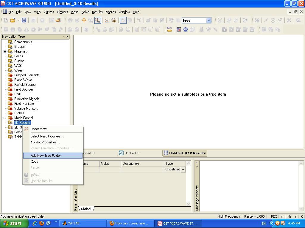
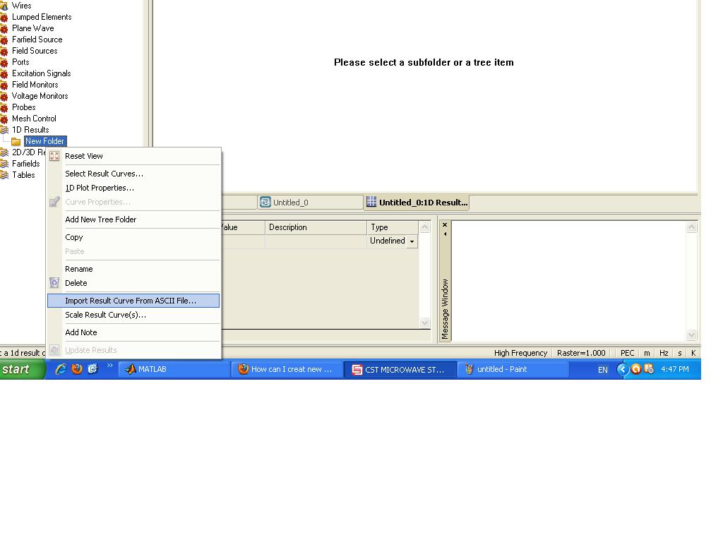
from Navigation Tree>1D results>(Right clik)>Import Results Curves From ASCII files
be happy
@myazdi83
i am sorry but i cant find Import Results Curves From ASCII files ?

Many thanks
OK, first create a New Folder and then do it, like this:


http://images.elektroda.net/48_1329053013.jpg
http://images.elektroda.net/21_1329053013.jpg
---------- Post added at 14:24 ---------- Previous post was at 14:24 ----------
OK, first create a New Folder and then do it, like this:


http://images.elektroda.net/48_1329053013.jpg
http://images.elektroda.net/21_1329053013.jpg
thanks myazdi83 thanks for your help
@myazdi83
how can we update CST parameter via VBA ? and can run the T-solver with the updated parameters ?
Regards...
If the defined parameters are global, they will be updated when you define a parameter sweep in T-solver.
Regards.
hello
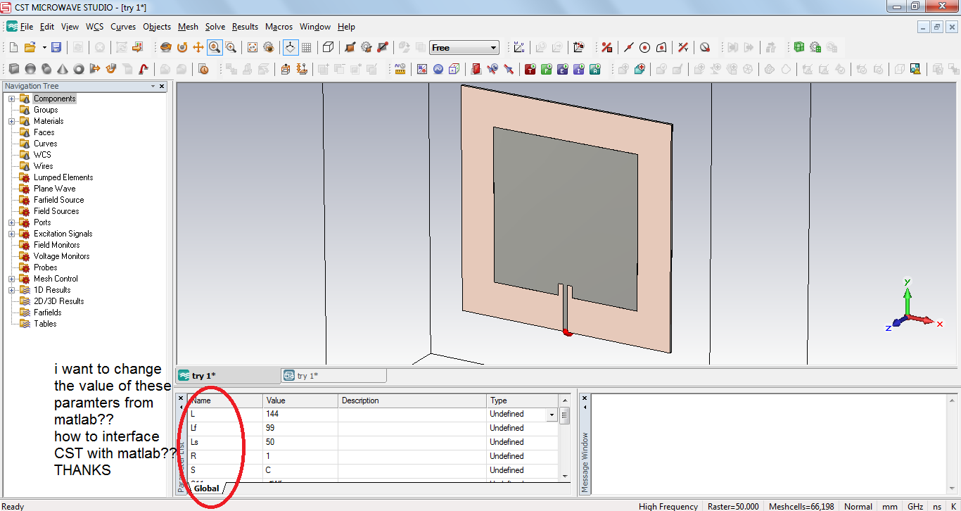
when i asked about importing information to CST i meant that i want to change the parameters from MATLAB ?

but they are global already ... do you know a VBA code to update the parameters and run T-Solver with the new parameters
i try to start the T-Solver after making parameter sweep by this code
Solver.Start
Save
but it get the result from the old parameters (i.e before parameter sweep)
thank you ..
Regards...
hi everybody
i have a problem with cst output file
when i run my script code with FDsolver(i use floquetprot & unit cell) i got some result like " %SZmax(1),Zmax(1)% versus Passes in dB.tab".
i want link cst & MATLAB then it should be txt file. CST'output should be .sig file to have ASCII outpot then i got error and i cant get outpot in txt file.i should do it with vba code. pleaaaaaaaaaaaase help me:( its emergency
- Error in creating symbol's layout (packaging) in ADS
- How would I create an LNA layout design when using the s2p file on the schematic?
- ASITIC Balun/Transformer Creation
- How to create RF integrated circuit? From project to wafer and production.
- How to create Schottky diode model in ADS?
- recreating chebychev coefficient from an article
