Stepped Impedance Lowpass Filter in ADS
时间:04-06
整理:3721RD
点击:
Hi..
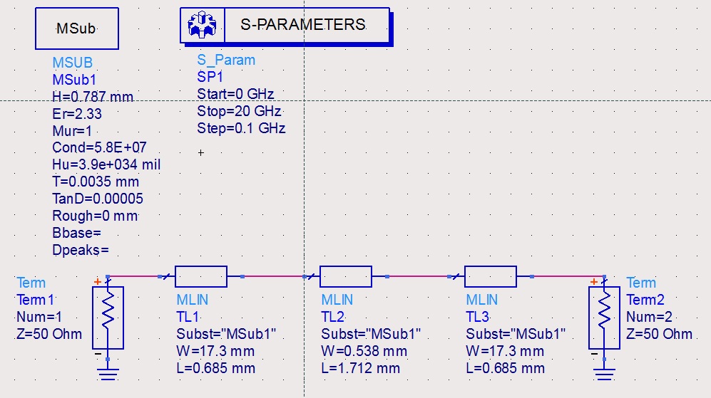
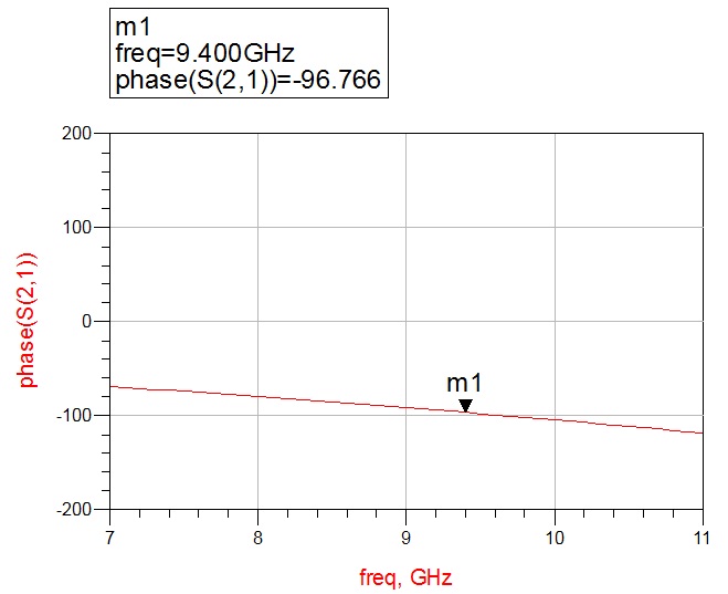
i'm currently designing LPF using stepped impedance that operate at 9.4 GHz and also i want my LPF have constant 90° phase shift at 9.4 GHz
so after i have the L-C value, i transform it to microstrip with
dielectric constant (εr) = 2.33
dielectric thickness (h) = 0.787 mm
and
Zlow = 10 Ω
Zhi = 110 Ω
so when i simulate it using schematic in ADS i get very good output,
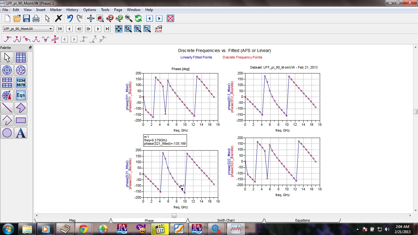
but when i simulate it in ADS layout using microwave simulation i can't get the exact result like the one i simulate using schematic
anyone has an idea?
here's a picture
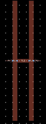

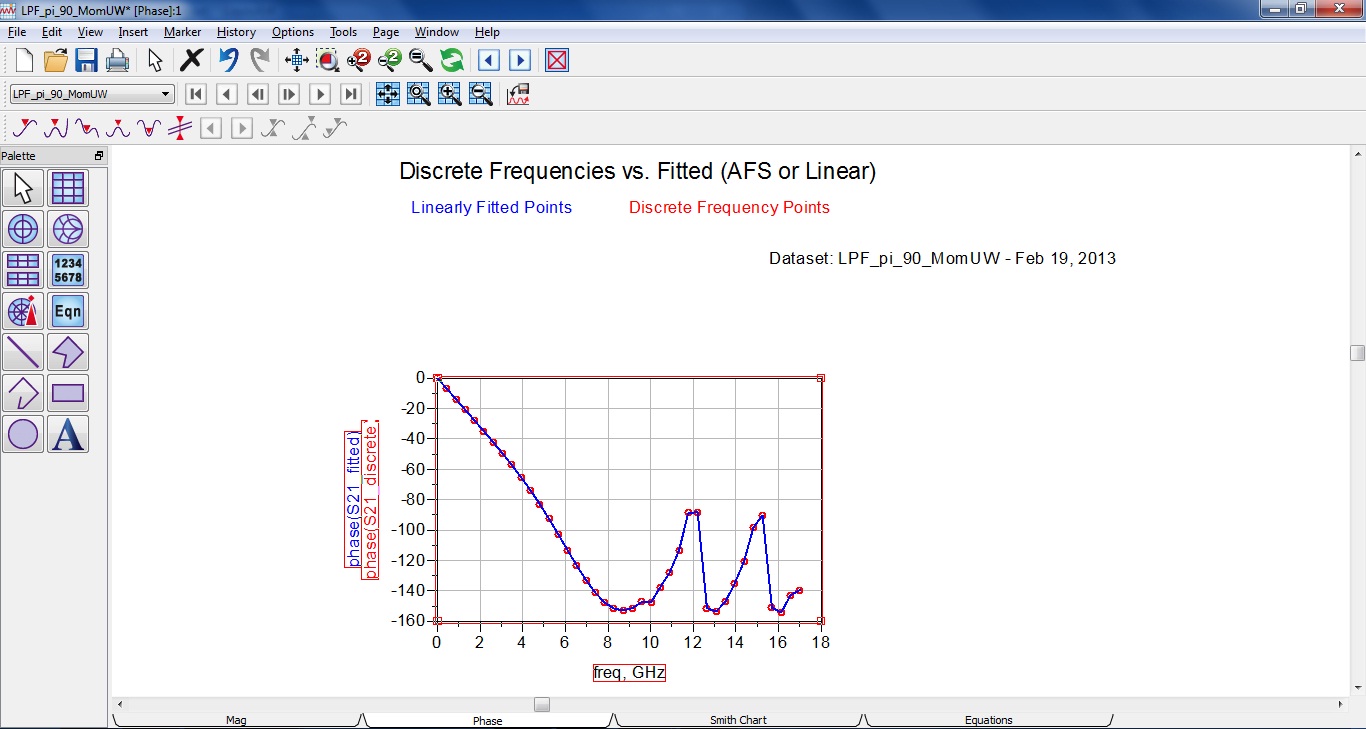
Ports are very close therefore there may be a calibration error because of coupling.Instead of that, connect the ports to extended MS Lines with 50 Ohm to push out the ports each other.
Hi Big Boss
thx for the reply
but how to decide the length of the 50 ohm ms line? i tried to use linecalc in ads and tried an arbitrary length of microstrip line then i simulate it but the result is still far from the scematic result.
Impedance Stepped Lowpass 相关文章:
- Output Impedance Of a Triple cascode
- How to make image impedance equal
- Input and output impedance matching in Distributed amplifier
- Characteristic impedance of combination of CPWG and stripline on inner layers
- Problem of impedance matching of Gilbert cell mixer
- Input impedance of transmission lines connected in cascade
