radiation pattern in HFSS
i guess i found the solution myself.after analyzing,go to HFSS>RESULTS>FAR FIELD >RADIATION PATTERN.
Hi,
Can anybody help me.....pls answer the questions, I am new user of HFSS, using v10 !
1. What solution type I should select to simulate an microstrip antenna?
2. What values of theta and phi should I put in the radiation setup to get good results?
3. How to see the current distribution?
Thanks
Hello,
1. Use Driven Model with a waveguide port
2. I think the stanard values are ok
3. You can plot the J-field under the "Field Overlays"
hi.
1- for microstrip better using the lump port
2- for phi and theta the step of 5 is good
3-for current as flanello said
Why is using a lumped port better?
If you have a microstrip antenna with a microstrip feed line the waveguide port would be ideal?
The lumped port is good if you have a feed point in the patch, for example with a coaxial cable.
hi
no thats not write for patch antenna better u use wave port for coaxial
for more information use antenna design kit samples
Thanks for your response :)
As example given in the HFSS Handbook, they have used waveport for microstrip antennas with coaxial probe feed, I am also doing that!
one more question...How I can see the E-plane and H-plane in HFSS?
waiting to hear from you...:)
hi
go result /far field /radiation pattern / gain/ gain phi and gain theta
Hi,
So how i can see the Gain in rectangular plot over a range of frequency, I want to see the peak gain...
Could anyone help me,pls... :)
Bless u
hi
at first you should define your antenna radiation direction and then u change the sweep to the frequency and define theta and phi the simulated your antenna
Create a rectangular plot with far fields.
For the sweep select all frequencies and one theta and phi angle. Which one doesn't matter since you want the peak gain.
In the y values select antenna parameters and then peak gain.
Hi,
I'm looking for two different plots for my rectangular patch antenna on HFSS.
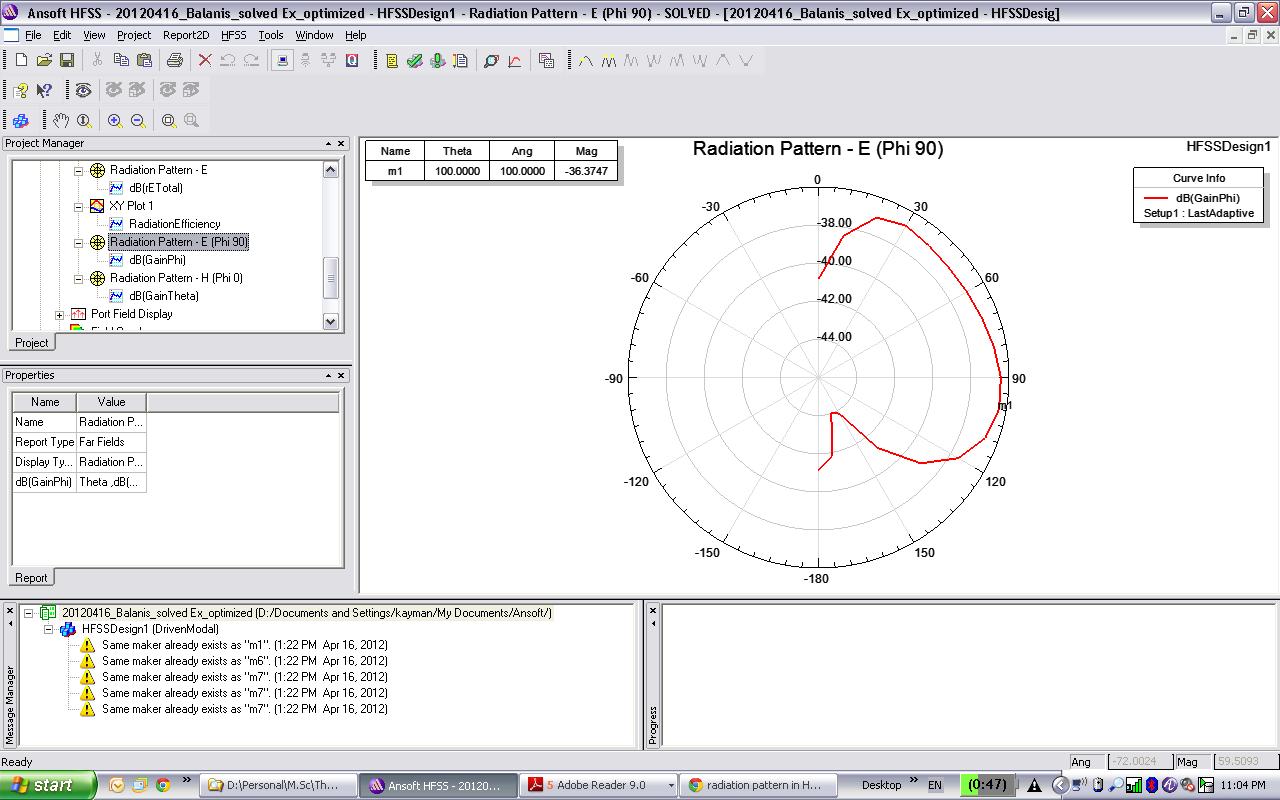
1) E-plane
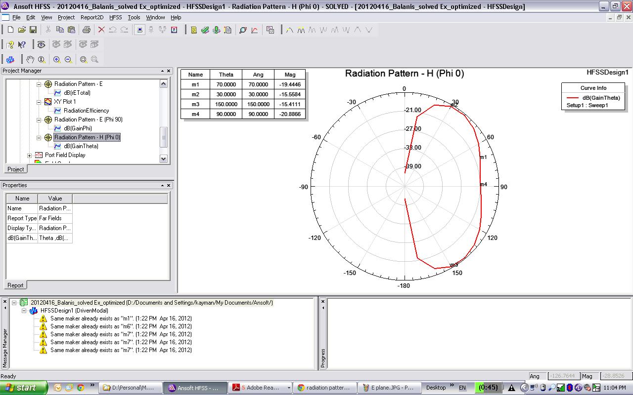
2) H-plane
I've been able to get results such as Gain, Directivity, S11, etc... but haven't been able to get the correct E&H radiation plots.
Thanks:)
Khaled
go result /far field /radiation pattern / gain/ gain phi and gain theta
Hi,
But then this is the output I get!?
Theta as primary sweep and all values, phi=0/90.
See the pattern for one frequency only.
Best luck :)
Hey,
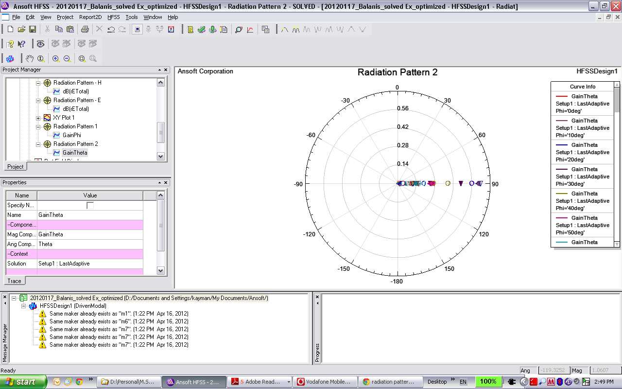
I followed your steps, do these look like good results? Appreciating your feedback.
Thanks :)
Khaled
The straight lines indicate that you have not enough points to draw a smother diagram. How many Theta points do you have?
Check the settings under Radiation->Infinte Sphere, perhaps you need to increase the number of points.
Radiation->Infinte Sphere>>change the theta settings from -180 to 180 or 0 to 360 degree.
And check the step settings. I think 10 degrees is the standard value, but perhaps you need a higher step size.
- Radiation pattern of an inverted F antenna IFA
- Real time plotting of radiation pattern using matlab
- Spurious radiation and surface waves in MSP Antenna
- Antenna Radiation pattern multi-lobed and directional with increase in ground plane!
- Improving radiation performance by using a mutual coupled antenna
- Radiation Pattern Check