HFSS Help (Urgent ).
I need to Know How to Simulate This Coaxial Cable On this Antenna with HFSS
need to Know the steps ,...step by step ,..and the Coax. Geometry
It's Urgent Please Any One
ANY ONE ! please it's Too Urgent ":(
Hi Ahmed,
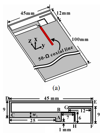
The illustration isn't very clear, it doesn't seem normal having a coaxial cable lying flat on the ground plane! Or is the gray part your substrate (in that case I would assume the feed is a microstrip line, not a coaxial probe).
Anyways the antenna structure you have looks like an IFA (Inverted F-shaped Antenna). I'm designing PIFA antennas in CST and the feed I'm using is always a discrete lumped port.
In your case you can simply try applying a lumped port between the ground (at the 100mm mark) extending 1mm towards your antenna structure.
if you want to simulate apply Extension to probe port then check your results
there is always an error Guys !
i don't understand the Concept itself ,...
How To feed This antenna ( Rectangle between the antenna and ground and assign it as wave port !)
or i should simulate a Coaxcail cable ( Feed pin + coax pin + Coax + port cap ) !
This is The antenna and the paper with out feed ,..please Help me with the Feed
Desktop.rar
None of the above, just simulate a lumped port (as mentioned above) with lenght 1mm between the ground plane and point A of the antenna. Try it out, in CST it works.
could you plz try it :(
i tried every thing i swear and still can't get S- Parameter
hi,im attaching d file which contain the probe feed method,which wiil help you.
if there is error, then it can't give u results. plz remove the errors
I opened your file and tried applying a lumped port, but it seems my skills are still rusty on HFSS. But if you can upload your file using CST I'd be more than glad to help out.
Hope there's someone here with better HFSS skills that can assist you on that.
Here's the updated design.
I cannot see any file in this post. If you provide a .hfss file, I can check.
dear pal,
i am using HFSS. may i help you ?
- - - Updated - - -
THAT is the CST file
hi
i have uploaded file .plz check
send ur design...
so you just want a design of a probe fed patch antenna ?
I have attached a .hfss file which was generated using the hfss adk.
- the feeding should be correctly set up in this file
- you can modify the frequency/substrate/patch to suit your case
can u tell me how to see polarization in hfss
why are you making two radiation boundary ?
That is a common trick used. If you look carefully, there is still only one radiation boundary (the outer box). The inner box does not have any boundary conditions applied on it. Its purpose is to concentrate the meshing of the model in the inner region, hopefully reducing the simulation time. Incidentally, it is also useful for the E-vector plotting described below.
In order to 'see' the polarization, follow the steps below:
Select the outer box 'AirBox' -> Right click -> Plot fields -> E -> Vector_E -> Press 'Done' with default settings. After this, you should be able to see a bunch of arrows in your model window denoting the direction of the E-field. This would be the polarization direction. Under Field Overlays -> E field, you can right click Vector_E1 and select Animate. Swept variable: Phase from 0 to 350 deg. This will help you to visualize the variation of the E-vector with input phase, thus generating the polarization ellipse (in this case a line).
There are easier ways to quantitatively judge the polarization. Under Radiation, right click on the setup infSphere -> Compute Antenna parameters. Select: Setup1: LastAdaptive and press Ok. You should be able to read off the information about rE in X, Y, Z, LHCP, RHCP components as well as other important antenna parameters.
when i am running given file, warning is coming?
- - - Updated - - -
when i am running given file, warning is coming?
I have only used radiating boundary condition in HFSS and not PML. So cannot be of much help regarding errors of conflicting PML and Perf E
You might want to rethink about simulating all the way from 1 - 10 GHz for a patch of 6 GHz. A patch has a typical bandwidth of < 5%. So 5 - 7 GHz should be more than enough to capture the resonance frequency, provided your initial design was for 6 GHz.
I have tried to modify your file to work with a radiating boundary bounding box instead. the distance of the radiating boundary should be atleast lambda/4 away from surface at the lowest frequency (in my case, starting from 5 GHz, I set it to be at least 15 mm away). It also helps reduce the simulation time drastically.
After simulation, the resonance frequency is at about 5.8 GHz.