rectangular patch antenna design using coaxial probe feed
can u plz help in designing a simple rectangular patch antenna with coaxial probe feed using ansoft hfss.also plz state the position of probe feed,length of the patch,ground,width of the patch,ground,height of the substrate,dielectric constant of the substrate and also their positions to place them.the design should be effective in reducing the return loss i.e, dB s(waveport,waveport).i'm confused because what i designed had a positive value in the dB s(waveport,waveport) graph.
Hello,
There is a lot of links for simple rectangular patch,
so many books, balanis, modern antenna design ans so on.
there is also there good tutorial
http://www.zen118213.zen.co.uk/Syste...ch_Antenna.pdf
you can follow this one.
but help with simulation software you can find only on their website. Also i am sure you can find some patch antenna in their example!
WASABI
Good Luck
hello wasabi,
Thank u so much for ur guidance.
hello wasabi.
the paper is of much use to a newbie like me.
thanx a lot
what about positive return loss?!
thank you sir.....
dear Mac.feri
positive return loss? it must be below -40 or -50 db.
i wonder there is something wrong with your design.
please upload your HFSS and let me check your design.
hope it can help you doing your assignment
" i recently designed a rectangular patch antenna with -26db return loss at resonant frequency of 1.5 Ghz. for that length and width and height of substrate is(75.944,88.244,1.524). for ground plane(75.944,88.244,0.1). and patch(66.8,79.1,0.1) and probe location (10,0,0)
If I recall correctly, there's an example of a coaxial feed patch antenna in the HFSS manual.
Dave
hi everyone. i am modeling an rectangular patch antenna in cst mws. i designed it following the tutorial in cst help. one thing that's bothering me is the position of the coaxial feed. i tryed to find the best point by sweeping that parameter, but my mentor insists that i find a suitable ration betwen the feed position and overall length of the patch. so what i'm asking is if someone knows is there any equation with which i can calculate this or maybe a ratio previously determined by some tests?
btw, i've tryed searching barthia and bahl's book but with no luck. also, one more quick question: is it better to use discrete or waveguide port? thank you for your help!
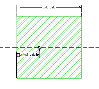
This is from a german language textbook (Frank Gustrau, "Hochfrequenztechnik") and quotes Garg, Bathia et al "Micostrip antenna design handbook" as the source.
xf is the offset from the end of the patch
yf is the offset from the side (half patch witdth = centered)


From my experience, the equation gives a good starting point. I use it in a Sonnet EM model that syntheses the patch antenna model, based on textbook equations.
this is excellent! just what i was looking for. now i have a theoretical background to support why the selected position was chosen. i calculated the result by hand now and got a good result..i'll try the formula in the simulation afternoon. thank you!
Hi,
Can you email me the pdf file mentioned above because the link doesn't seem to work? I'm trying to design a patch ant with coax feed.
grdnzzz@hotmail.com
Thanks.
helps a lot.. what ur personal email id? i also have some other queries.. please...reply
Sorry, my company does personal email support only for paying customers.
thankyou for reply..!
ok. its absolutely fine.. i am ready to pay as per your rules.
i am a student of M.Tech in India.
i am currently working on Antennas [keywords : reconfigurable antennas, microstrip, multiband, slots , mobile communication band]
how could you help me ?
give me a detailed procedure how can i pay you.. and access you..!
my e-mail id is : antenna.freaks@gmail.com
Concerning the coaxial feed for a rectangular patch antenna... how do I determine the radius for the inner and outer conductors? and what about the choice of dielectrics between both conductors?
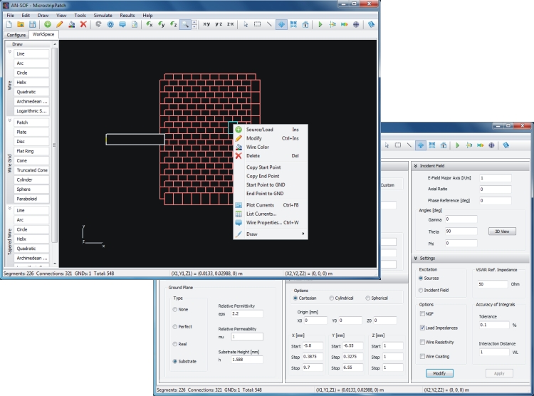
Here you have a good software to simulate a rectangular patch.

Do you have any tutorials for this software?
In this link you will find a quick guide for simulating a rectangular patch connected to a printed dipole. The microstrip antenna is fed by a vertical vias that is used to model the coaxial probe.
