microwave filter simulation error ?
I have designed low pass microwave filter with cut off frequency of 3.2 GHZ , I have problem with the result from simulation(S21) .
please can anyone help me ?
project7.zip
any help ?
I do not have hfss simulation setup. can u capture screenshots of structure and simulation results?
Regards.
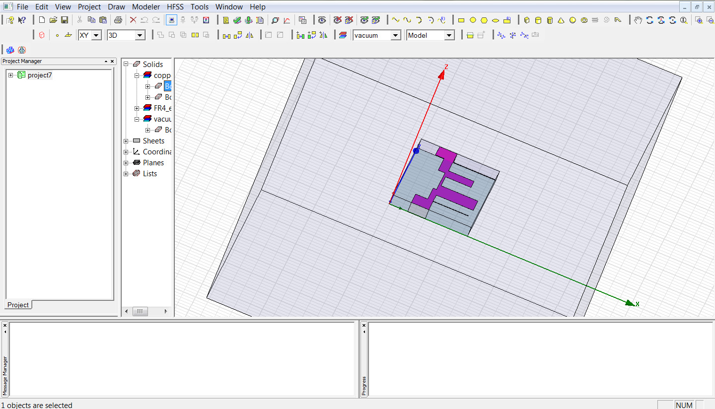
Make air cavity x-y dimensions same as substrate.
Increase port z dimension 2 to 3 mm more. better make circuit symmetry though it is not problem.
Hope this works. share more pictures if it could not sove the problem. I guess air bottom is not defined as conductor. or better keep a gnd shape beneath substrate.
Regards.
sorry , Should bottom of vacuum box be conductor ?
if you define Air as radiation boundary then its good having vacuum box as conductor, or at least bottom of substrate.
Remember for microstrip we need bottom ground
ah , yes, I have ground substrate in the design
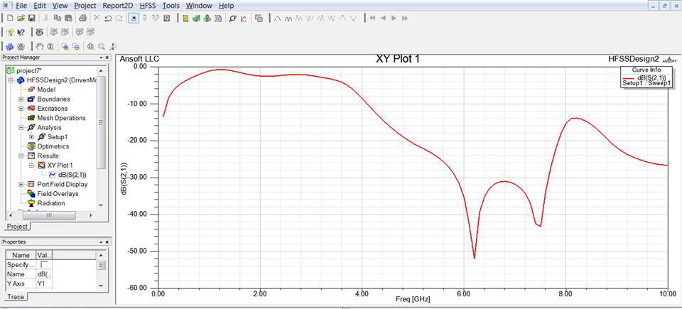
I perform the simulation now , but I do not know , what is the reason for resulting this curve ?
can u share screenshot of expanded/exploded content on project7 that indicarte ports, results etc.
try increased port size on y direction also.
Also share expanded screen shot on materials sheets etc.
Regards.
how can I increase lumped port in y-direction , it is sheet in x-z axis ?
substrate material-->FR_4
ground material--> copper
microstrip and stubs --->copper
radiation box --> vacuum
lumped port-->sheet
I can not understand without pictures.
can u click on all + symbols and make visible of all properties in HFSS window?
if I obseve on the left side of the picture i see only project7 and every thing is hidden.
Make me to understand.
can u use wave guide port? If you learn this i guess you solved it.
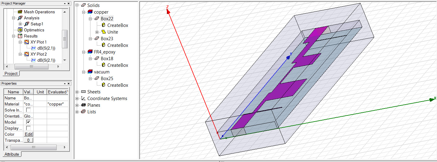
show me the vaccume properties. make 0,0,0 as corner
when I made it at 0,0,0 , HFSS error : objects intersect
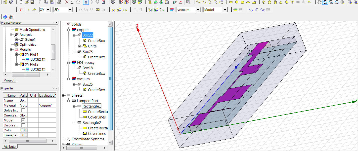
show me pictures otherwise i can not help
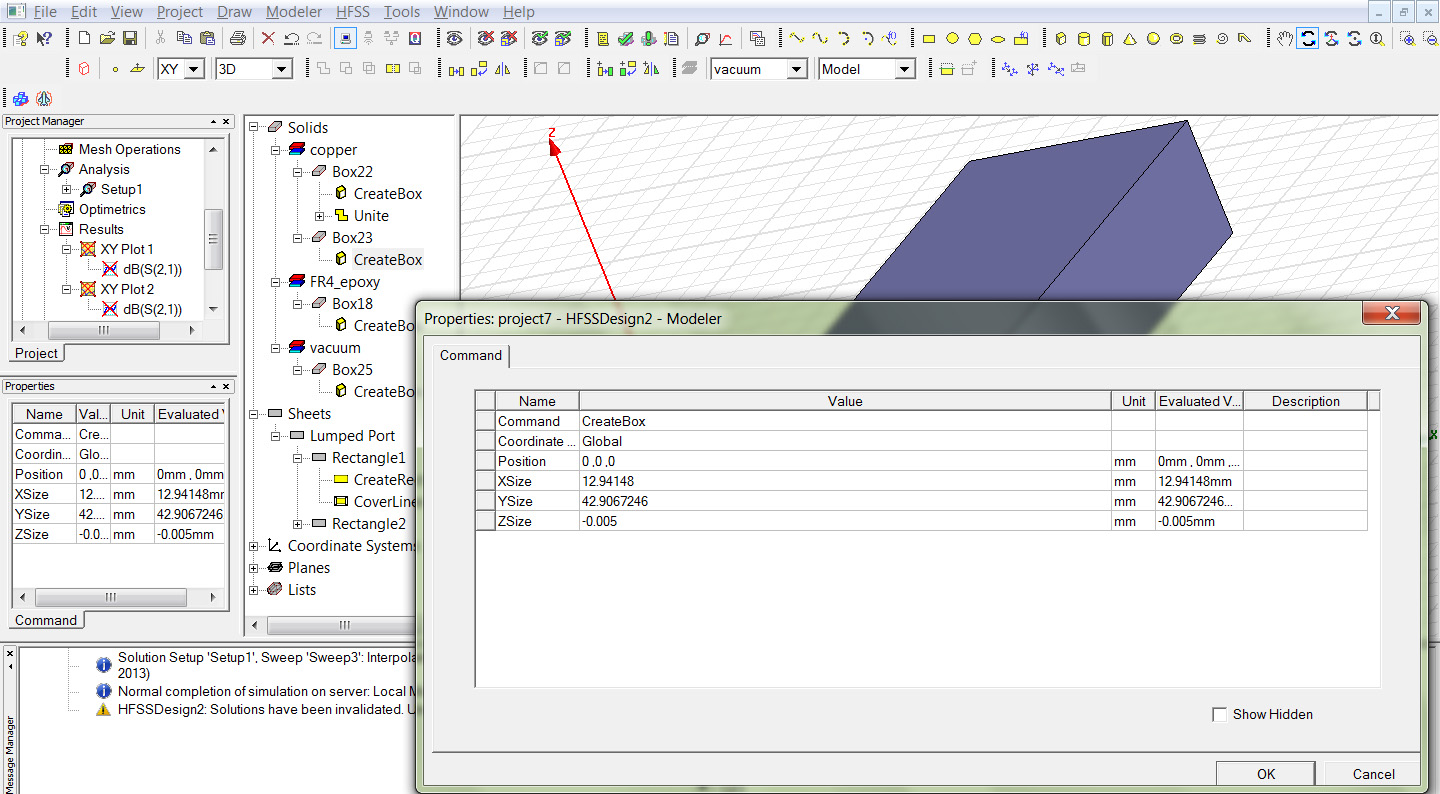
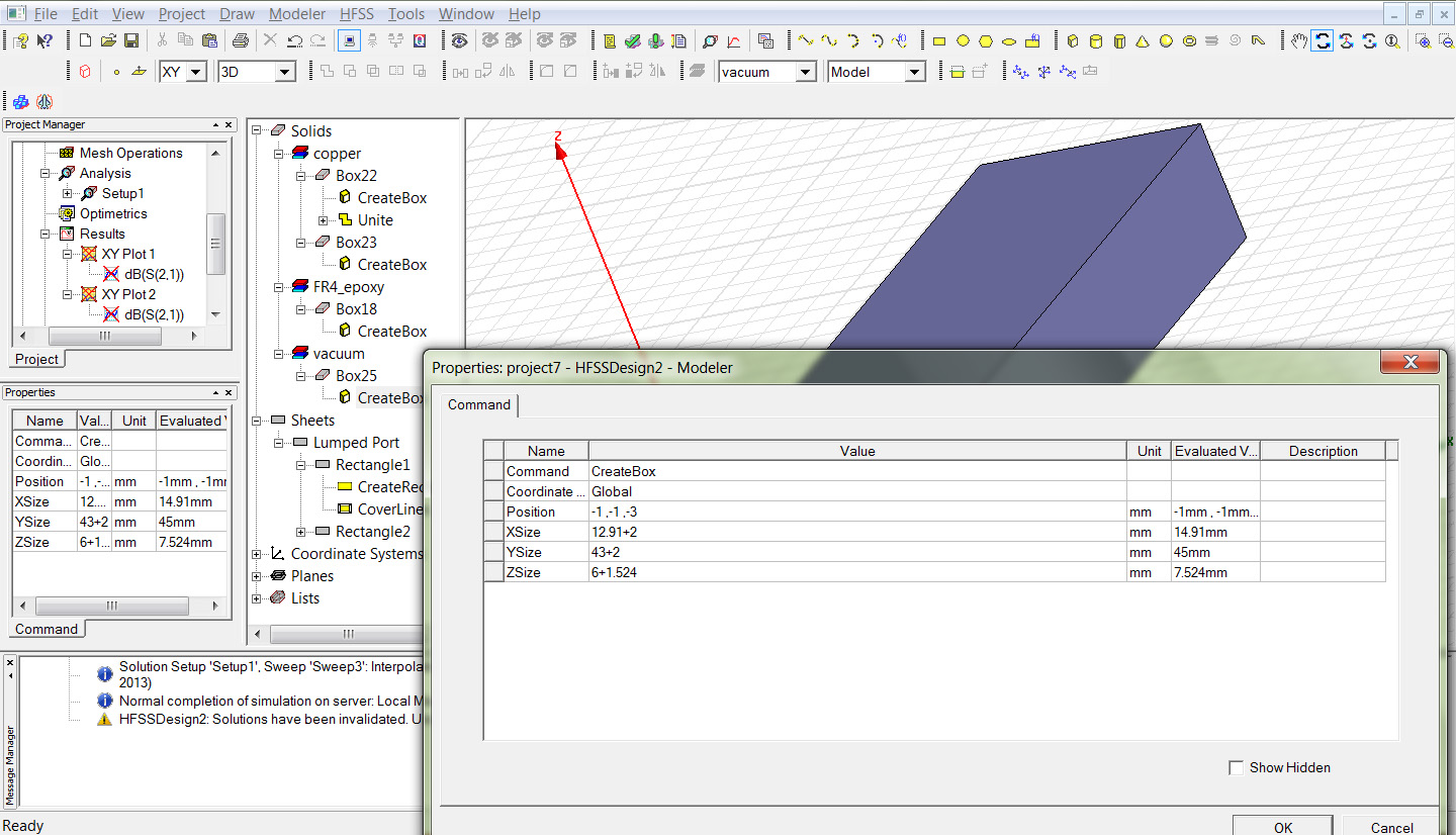
show me box 23 and box 25 properties
box 23
box 25
got it
make changes in z co-ordinates to -0.005 from existing -3. you should not get error this time
can u share me zoomed version of project properties?
it contains ports, fileds, results, boundaries etc.
if i am correct you imported the structure form other designs like ADS.
make co ordinate entries same as original design for vacuum i.e. 12.94148 etc shown in the pictures.
repeat the exercise for all data entries like 42.9067246
There is discontinuity in the ports. better practice is chop the design and continue with coarse grid than fine grid.
