radar receiver for warning drive (help) ,how does it work


thanks !
The schematic shows a simple sweep-frequency receiver that can detect RF signals. Without frequency specifications I can only estimate that it may cover UHF to L-band frequency.
hello! jiripolivka , thank you at first , it works at K-band and Ka-band, used for Driving warning,the last schematic as follows:

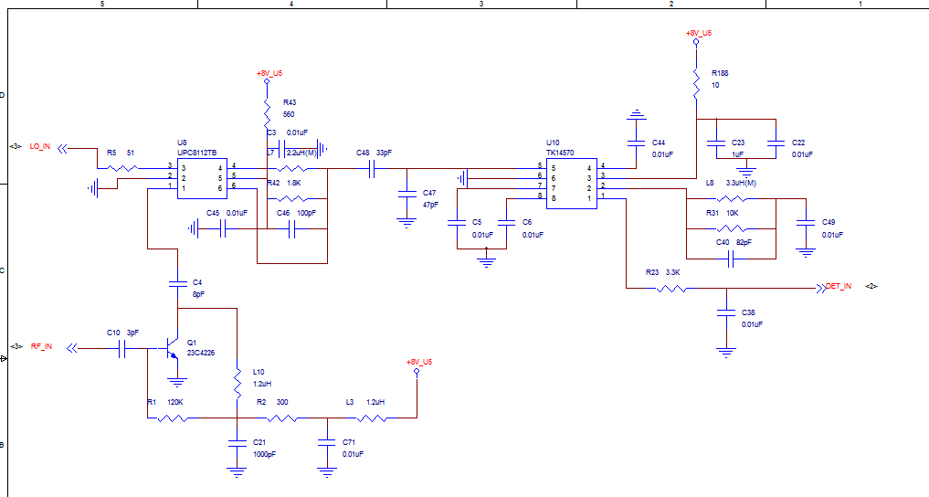
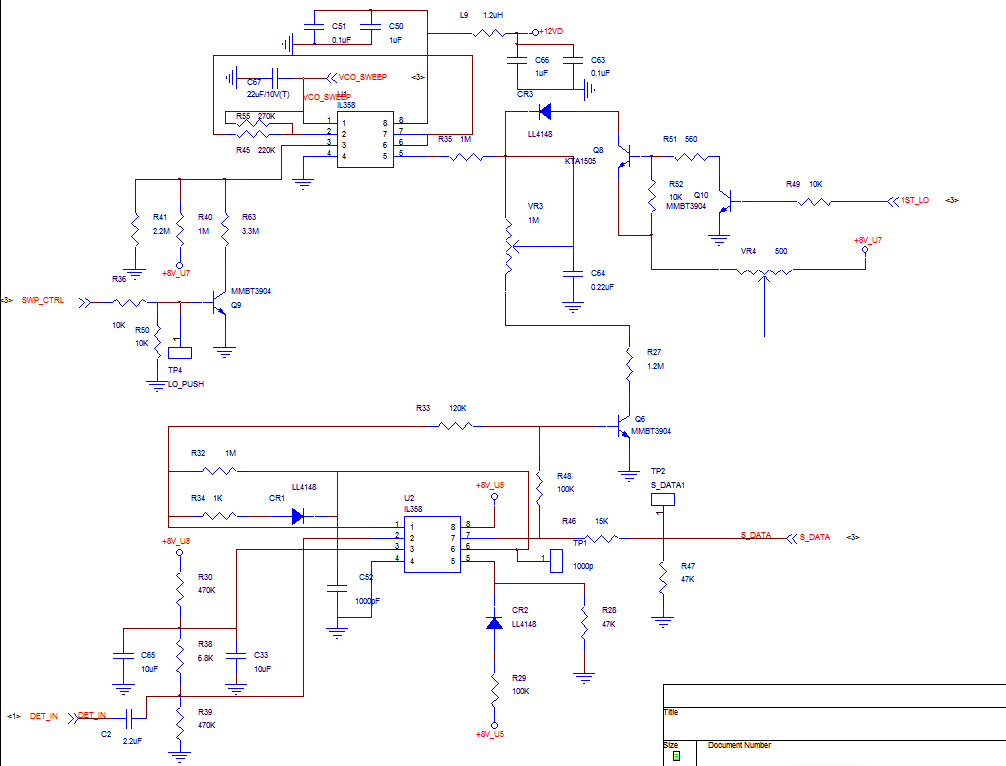
The first schematic shows a down converter using a LO and amplified RF to obtain an IF amplified in the right-hand IC to "det out". On the second schematic, on the top it is a circuit controlling a VCO to make it sweep for the above converter. On bottom it is an IF detector and video amplifier of a beat IF signal created when the LO frequency crosses the radar frequency. The third schematic shows a uP controlling all functions, and a double RF oscillator for a second(?) LO.
Police radars operate an a selected frequency and use CW to measure target car speed. To detect their signal an unknown frequency requires the receiver to sweep over the frequency band where radar signal is expected. When those two signals cross, it creates a beat (IF) signal pulse which is amplified and displayed to show a radar signal is detected.
If you want more details, find IC makers and in their website they indicate specifications and evaluation board schematics for similar functions.
Well it is useless now since 99% of all police departments switched to LIDAR which is based on reflected laser beam, more precise and harder to jam and detect (laser beam has very narrow spread). I guess old school police radar can be classified as retro electronics now.
hello, apolkhanov,at first , i want to say thanks to you , in my conutry, police is still use K-band and Ka-band to measure car's speed, so we still need to do something for the driver and avoid their was fined for speeding, may you happy!
hello! jiripolivka , sorry to disturb you again, Can you explain to me the specific signal flow and the specific parameters of the calculation, such as " 'RF_IN ' amplification through Q1(how it works of Q1), and then through U8 mixer, to obtain an IF signal, "(What is the frequency of LO_IN).... may you happy!
The first picture shows on the top a mixer down converter which receives the LO signal generated by VCO on the second schematic. The RF input is amplified in Q1 before entering the mixer IC.
The second IC is an IF or beat-frequency amplifier, apparently a video amplifier covering ~1 kHz to several MHz. When the fixed radar frequency and swept LO frequency cross or get close together, the video amplifier generates a short pulse which through the uP PIC.... generates a display indicating radar signal hitting the detector in your car.
The best advice to avoid problems is to keep the speed under indicated limits. Then you do not need radar or Lidar detector.
On the other hand, in California I was fined for exceeding 75 mph speed by a fake police report. I did not speed and the police never used a radar, though a judge fined me for no reason. So even having a radar detector, a citizen is lost due to criminals being employed by police.
hello, jiripolivka, i'm glad to hear from you, could you show me more detailed!
In our country,the speed limit in some places are not very reasonable, so the equipment is still necessary,hee hee.
Maybe the police want you to pay for his drink, so just fined you , hee hee, my english is poor and are the Chinese-style english,can you understand?
By the way, what aspect are you in ,forgive my intrusion!
Happy a weekend!
In China, there are some companies are producing such radar, you can buy one and study it. Sometimes copy it at first.
Most design was from taiwan.
hello tony_1th i'm come from China,hee hee
