Input impedance over a frequency range in ADS
I am simulating a network given in a book using ADS.I have to plot the input impedance over a frequncy range.
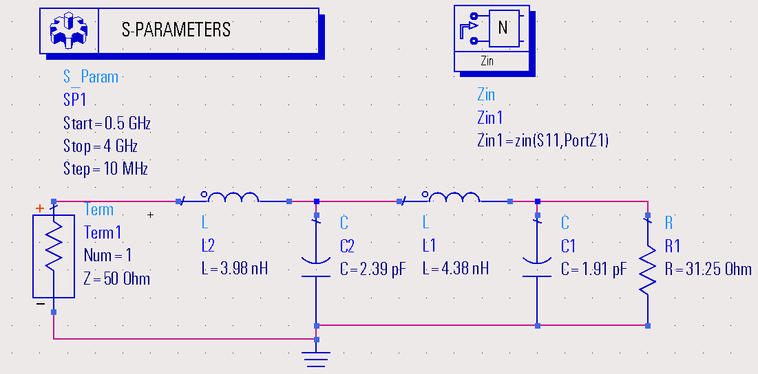
See the following setup to I created do that:
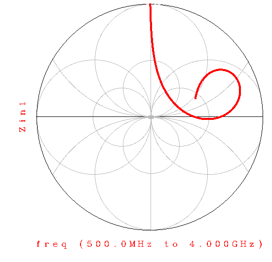
I am getting following result:
Kindly help me with following two questions:
(1) What to do so that it resembles with the answer given in the book (hopefully that is correct!), see below

( why ads is showing smith chart from four directions)
(2) could you kindly explain the arguements used in Zin block? I learned it in some tutorial to add zin block but I couldn't find any explanation thereof.
Thanks.
Zin is not equal to S11..
At first graph, you drawn Zin and Zin is outside of Smith Chart.
But at second one, S11 has been drawn on Smtih Chart therefore you see the difference.
If you draw S11 on Smith Chart, you will see the same curve.
Zin block calculates Input Impedance by aid of s-parameters of circuit.
Zin=Zo[(1+S11)/(1-S11)]
BigBoss, Thank you very much for your reply. In RFCD book by Ludwig/Bogdanov, at pn-133 this plot (2nd figure) appears. They claim it to be Zin. So I should consider that wrong.
Couple of more questions-
In the first figure, when I put marker at 2GHz, It gives Zin1=49.774/-0.077, impedance=-52.050-j0.003. Hand calculaton says it should be around 50ohm. So it looks Ok.
What is that -0.077 in Zin1? Phase, right?
About Zin block, ads help says
"Given a reflection coefficient and the reference impedance, this measurement returns the input impedance looking into the measurement ports
Syntax
z = zin(Sii, Z) ".
But in my setup PortZ1 comes as default in argument when I draged & dropped Zin block. Is PortZ1=term impedance?
It appears to me that I can use this Zin block to find output impedance, too. If yes, what should be the syntax? z=zin(S22,PortZ2) ?
Yes, imaginary part of Impedance in complex form.
Yes, if you have 2 or more ports, all you should have to define port index and Reference Characteristic impedance of this port.
I tried to use this formula in my Qucs project but it doesn't work correctly. What is my mistake? On bottom you can find comparison with ADS simulation. Please, advise me how to find the input impedance of this quarter-wavelength transmition line using S or Z parameters?

Look at carefully to the formulae, there isn't "mag" definition.
Zin is a "complex" impedance so that it's got real and imaginary part.At the first equation you have taken "mag" of S11 that is wrong and then you took again mag of Z11 that is also wrong.
implement the formulae correctly and you will see real and imaginary parts of the input impedance.
- Output Impedance Of a Triple cascode
- How to make image impedance equal
- Input and output impedance matching in Distributed amplifier
- Characteristic impedance of combination of CPWG and stripline on inner layers
- Problem of impedance matching of Gilbert cell mixer
- Input impedance of transmission lines connected in cascade