Perfect E Boundary in HFSS
时间:04-05
整理:3721RD
点击:
Hello,
I need your help about perfect E boundary in HFSS; I'm biginner in using this software, I tried to simulate an manufactured antenna, but I got a S11=-15 and when I used perfect E boundary in the upper faces of the conductor (copper , thickness 40 um) I got the right S11=-28 dB (-30 dB foe the manufactured antenna)
Any explications? what 's the right way to assign this boundary : in all faces of the condutor or only in the upper one?
I know that boundary E means that the E field E is perpendicular but I need more explinations, it is always obligatory to use it?
many thanks
the thickness of copper is 40 um, the boundary perfect E is assigned to the upper faces of the inverted F and the ground plane
waiting for your help
I need your help about perfect E boundary in HFSS; I'm biginner in using this software, I tried to simulate an manufactured antenna, but I got a S11=-15 and when I used perfect E boundary in the upper faces of the conductor (copper , thickness 40 um) I got the right S11=-28 dB (-30 dB foe the manufactured antenna)
Any explications? what 's the right way to assign this boundary : in all faces of the condutor or only in the upper one?
I know that boundary E means that the E field E is perpendicular but I need more explinations, it is always obligatory to use it?
many thanks
Don't assign boundaries to 3d objects in general unless it is the boundary condition, solids should be assigned a material. What type of antenna (patch, dipole, etc.)? pictures would help.
Thanks for your answer,
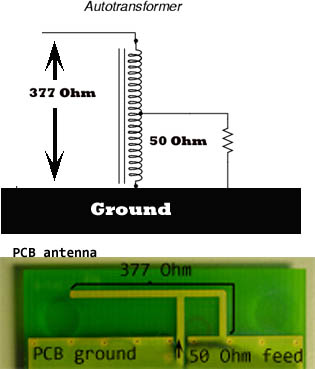
I havn't the desin under HFSS for the moment, but it's an inverted F antenna (IFA)
the antenna in the picture is not tne one that I tried to design, but it's look like it
the thickness of copper is 40 um, the boundary perfect E is assigned to the upper faces of the inverted F and the ground plane
waiting for your help