chip impedance value having on effect on antenna results
thanks
Resonance (when looking from a 50 Ohms port) is not required for the chip as the chip doesn't show a real load to the antenna. You need to have an almost conjugated match.
If the chip has an input impedance at operation of 40-j60 Ohms (just an example), your antenna should present 40+j60 Ohms to the chip to have a good power match. So when you simulate your antenna it should have Z = 40+j60 Ohms.
40-j60 Ohms is not best match for a 50 ohms based system, but for this example chip it is.
but as i mentioned that there is no change in result at any value of impedance i mean chip impedance is not effecting results
ok just tell me how do we assign impedance to the chip. i am doing it this way
assign boundaries --> impedance --> assign values and ok
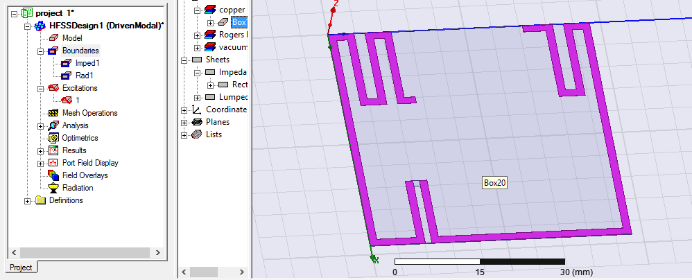
here is my antenna design
I don't know your software, so I don't how it treats complex source impedances.
Be careful assigning complex impedances to sources. If you do, check some simulations with manual calculations.
It is normal that when you change the source impedance that drives your antenna that, the antenna impedance doesn't change. I am still unsure about what you are doing with the antenna impedance and chip input impedance.
- Output Impedance Of a Triple cascode
- How to make image impedance equal
- Input and output impedance matching in Distributed amplifier
- Characteristic impedance of combination of CPWG and stripline on inner layers
- Problem of impedance matching of Gilbert cell mixer
- Input impedance of transmission lines connected in cascade