2.4 GHz Wifi; RG-58/U coaxial cable with 50 Ohm impedance as Balun for Folded Dipole
I am building a 2.4 GHz Yagi-Uda directional antenna for Wifi. I use a RG-58/U coaxial cable with 50 Ohm. I use the Yagi calculator of VK5DJ as a guide: http://www.vk5dj.com/yagi.html
The folded dipole has an impedance of 288 Ohm. The transmission line has an impedance of 50 Ohm. The impedances do not match, so impedance matching is needed to avoid power loss due to reflection.
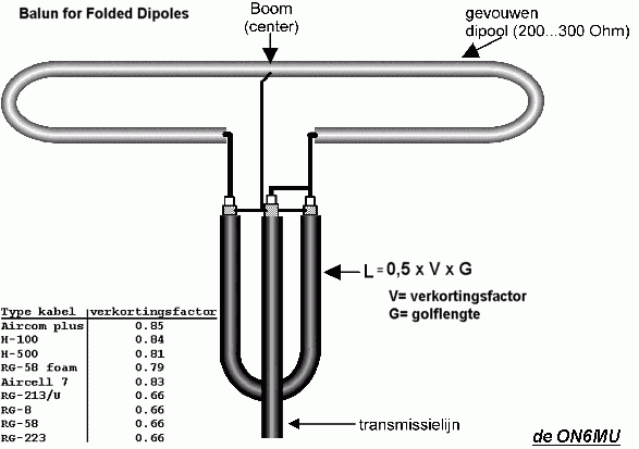
For 2442 MHz the Yagi calculator of VK5DJ recommends a 4.1 cm long RG-58C coaxial cable as a Balun.

Unfortunately the minimum bending radius of RG-58/U coaxial cable is 25.4 mm. Bending a 4.1 cm long RG-58/U for 180 degrees violates the minimum bending radius and probably changes the properties of the cable. Now I understand why it is a calculator for VHF/UHF. Now I am stuck.


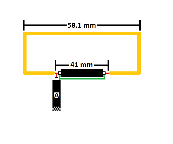
I have an idea how to avoid bending the 4.1 cm coax cable for 180 degree. But this requires that the core of cable A is at least 4.1 cm shorter than the shield of this cable. But does this changes the properties of the coax cable?

Or should I use conductors and capacitors instead of a coaxial cable for impedance matching?
I am stuck. This is the first antenna I am building and don't know how to continue.
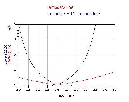
Instead of the 1/2 lambda line, you can also use 3/2 lambda.
Can you explain why this is the case volker?
Why does a 1/2 lambda line work? Maybe because this way the reflected wave we want to avoid gets wiped out by itself?
If so, would this imply that every n*1/2 lambda line with would work? Is this correct?
"Wiping reflected wave out" feels stragen. Isn't the goal of Impedance Matching to avoid at all that such reflected wave is generated? I am still a bit confused. Currently I am reading a lot about Impedance Matching, Smith Charts, L- Pi- T-networks; and I am still missing the big picture.
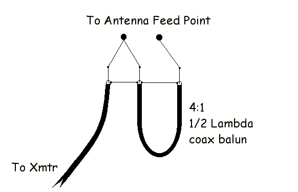
1/2 lambda length of the coaxial cable balun act as 4:1 for impedance, and 2:1 for voltage.
3/2 lambda may work, but you don't get 4:1 impedance ratio anymore.
At 2.4 GHz I would recommend do not use a folded dipole for the driven element, because anyway the bandwidth of a standard 1/2 lambda dipole (~73 ohms) at that frequency usually covers the desire bandwidth.
The balun would be simpler as a: sleeve, or gamma, or resonant stub, etc. Check the net for various examples.
http://dg7ybn.de/BC_numbers/Pics/ske...h_too_long.gif
That's nonsense.
This balun type requires simple transmission line math. The 4:1 impedance ratio is because the 1/2 lambda line creates a 180° phase difference at the other end. We now have twice the voltage at half the current -> 4:1 impedance ratio. Now if we add another 360° of phase, that changes nothing at the center frequency. We still have opposite polarity as desired. However, the usable bandwidth gets narrower, because the phase deviation from the ideal 180° changes more rapidly if we add multiples of 360°.

lambda/2 + n * lambda. We need to create opposite polarity at both ends of the line.
A practical concern would be the precision of the phase offset, with all the extra length to connect the center conductor and shield. That would be easier with really thin coax.
First of all, really thin coax will have huge insertion loss and uncontrolled phase change, and the structure would be practically useless.
So, if we add and add tens of lambda lines, we get a "razor blade" sharp VSWR? That's nonsense. For decades, nobody use other than lambda/2 for this kind of coax line balun.
Huge insertion loss for an extra length of 8cm? Really?
Uncontrolled phase with a thin cable like RG174 or RG178? Why?
Yes, extra length means more rapid phase change vs. frequency. The usable frequency range where the impedance transformation works is smaller then. Nothing new about that.
It's simple transmission line theory.
BTW, theory also tells us that the "balun" reference that you linked in post #4 isn't a balun. It is just a quarter wavelength impedance transformation. The feed is still unbalanced, just with another impedance level.
The simple reason is that we only need lambda/2 for 180° phase shift. There is no electrical need to add an extra wavelength. And the practical downside of extra length is that the matching is more narrowband.
It is very hard for me to keep my promise, to never argue on the net.
I am afraid that you are wrong. The picture in my link above IT IS a balun.
As always I am trying to refer to the original post (now is about a folded dipole and 4:1 coax cable balun) the recommendation was to change the driven folded dipole to a simple dipole. In this situation sometime a balun is not needed, and usually the designers are using for a 2.4 GHz dipole a simple type of matching element, as I mentioned above.
Returning to the 4:1 coax cable balun, there is a very old golden rule that the 1/2 lambda balun shall be made ALWAYS from the same type of coax cable as the coax feeder. So, trying to bring into the equation thinner or thicker cables is nonsense.
RG174 is one of the crappiest coax cables that exist on the market, especially for applications where the phase change is important. For this cable the "simple transmission line theory" never applies.
Length of Coax Balun
The original voltage wave and the same voltage wave with 180 degree are in antiphase. This means destructive interference, and we have zero Volts? Combine a voltage wave with itself with 360 degree and the amplitudes add, so from V we get 2*V?
See http://en.wikipedia.org/wiki/Phase_%...ase_difference
This all feels strange. Guess I need to read and learn more about AC, voltage and current waves, and phase shifts due to reactanve of inductors or capacitors.
Alternative to coax: use capacitors and inductors
Can't I just use capacitors or inductors to create a Impedance Matching? If I do the math right, choose the right capacitors and/or inductors, I can solder anything I want and match the 50 Ohm coax to any antenna that I want. And if a Dipole has enough bandwidth "support" I would use that instead of a Folded Dipole. Matching 72 Ohm to a 50 Ohm transmission line should be easier than matching than 288 Ohm I guess!?!
In YouTube I found some lectures where it is a common method to model a coaxial cable with a resistor, a capacitor, a inductor, and a "conductance device"(?); and they are chained together to model a "long" transmission line, and a coaxial cable is just one type of transmission line. So why not use passive RLC-components? Or do I misunderstand something very wrong here?
Dipole Bandwidth and Length
2.4 GHz 802.11g Wifi uses frequencies 2402 to 2482 MHz. So the bandwidth used is 80 MHz and the center frequency is 2442 MHz. That is 2442 MHz +/- 40 MHz or 2442 MHz +/- 1,638%.
Unfortunately I cannot find any (reliable) information about the bandwidth a Dipole and Folded Dipole support; that is the frequency range around a center frequency where the VSWR is small. Does a Dipole covers +/- 1,64% bandwidth around a center frequency? If so I do not need to use a Folded Dipole.
In contrast, it is very easy to find information about Dipole length. For example according to radio-electronics.com a Dipole antenna for 2442 Hz with 1.5 mm diameter copper wire is 58,9mm long. I don't know if this information is reliable.
http://www.radio-electronics.com/inf...on-formula.php
Length = lambda/2 * A. A depends on ratio (lambda:wire diameter).
Lambda 122,76mm / 1,5mm = 81,84. Factor A is 0,96 (see graph at radio-electronics.com).
So Dipole length = 122,76/2 * 0,96 = 58,9248mm. Again, I don't know how reliable this information is.
Impedance of (Folded) Dipole
I think a Dipole has about 72 Ohm, a Folded Dipole exactly 288 Ohm. So I guess a 72 Ohm Dipole is "easier" for Impedance Matching?
No, the voltage between the two terminals is V1 - V2. If we have antiphase with V2=-V1, the voltage between the two terminals is V1 - (-V1) = 2*V1.
You can do that. It requires detailed knowledge of the non-ideal properties of real SMD devices (series inductance and self resonance of SMD cap etc.), but it can be done. It is done where a really small circuit is required, and transmission lines are not possible.
We agree that "balun" stands for balanced-unbalanced? Then, can you explain in technical terms how this circuit does convert the unbalanced coax input into a balanced output signal?
I love golden HAM rules. Any technical reason to supports that rule?
Really. Interesting. My lab experience doesn't supports that. I guess you consider it crappy because it is thin and lossy - but there's a reason why we have coax with different thickness. For short connections, it's ok at these frequencies, if we need a small coax to access small test points.
Cheers,
Volker DL5DAW
- What is the difference between small signal and large signal in mixer? and in OPamp?
- Simple overnight charger for 5 x AA batteries
- Charge for redesign of a receiver chain
- Enlarging microstrip antenna
- Measurement of rf energy harvesting rectifier circuit
- Residual energy calculation in MATLAB for nRF24L01 module
